|
|
Stations, Junctions, etc
Engine Sheds
Other
|
|
Railcars in Warwickshire
Use the links below to access the
following sections on this page:
back to
top
Railcar Experiments in Warwickshire
Since the beginning of the 20th century and until the 1950s,
a number of experimental motorised railcars trials take place within the
county. The primary driver in the development of the railcar was obviously
economics, particularly with, but not limited to, services on rural and lightly
loaded passenger services. As such developments were often supported by
companies associated with the motor industry it is not surprising that
businesses from Coventry were involved, initially with the Daimler Company and
then later by Armstrong Siddeley. The Daimler Company had, just prior to the
outbreak of the First World War, initiated its own design and from contemporary
press releases would appear to have been planning a series of railcars for a
major railway company which no name was given. Armstrong Siddeley's approach
was to be different and perhaps could be considered more sensible in that they
looked to partner with an existing supplier of railcars, namely Michelin of
France in the 1930s.
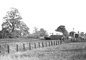
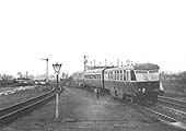
In fact the Michelin company was at the centre of two
initiatives, the Michelin Type 9 and Type 11 articulated railcars (see 'gwrwm421'
for a photograph of a Type 9 in action at Widney Manor) and the Coventry
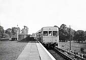
Pneumatic Rail Car promoted by Armstrong Siddeley from their Coventry base (see
'lnwrlave1349' for a photograph of it
standing at Leamington Avenue on a service to Nuneaton). As described by Darren
Kitson below, the development of both of these railcars should be seen as
evolutionary, with the Coventry Rail Car being a development, albeit radical,
of the Type 9 and 11 railcars. A major difference between the French railcars
and other railcars developed in the UK was the use of pneumatic tyres as a
means of making the ride much more comfortable for passengers as well as
reducing operating costs to both vehicle and track.
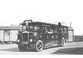
The other two significant trials were, the LMS'
collaboration with Karrier Motors of Huddersfield to develop the Ro-Railer, a
vehicle designed to operate on both rail and roads. A partnership which
according to JR Jennings, the SMJR line's archivist, was a surprise to some as
Karrier were running down their bus production having earned a poor reputation
for reliability in the 1920s. The other significant railcar development, albeit
initiated in London but quickly exploited with services from Snow Hill to
Cardiff, was the GWR's collaboration with Hardy Railmotors Limited, a
subsidiary of Associated Equipment Company Limited (AEC) with what was to
become a very successful series of railcars. With a total of thirty-eight
railcars being built between 1934 and 1942, this railcar was the most
successful vehicle until British Railways developed a number of different types
in the 1950s. An early prototype which was partially tested in the county
involved yet again AEC and Park Royal with the development of the BTU designed
lightweight railcars.
The advantage of railcars is principally their ability to be
started whenever it is required, or a few minutes before it is to be moved, or
stopped whenever its stationary for more than a few minutes. There was no
necessity, as with the steam powered railcars or locomotives, to start raising
steam a few hours beforehand, or to keep steam up all day nor was a need for a
fire-man or a skilled type of driver, as with the steam powered coach, as the
driving controls were relatively simple. Another factor with regard to the
experimentation of railcar development is the difference between power to
weight ratio of the two types and the savings that could be made.
As an example of savings being derived from the power to
weight ratio of motorised railcars, the first Micheline rail-coach tried in the
UK had an unladen weight of 5 tons; its seating capacity was twenty-four; which
works out at about 4 cwt of deadweight per passenger carried. A branch line
steam train capable of carrying 160 passengers weighs, when empty, about 135
tons, giving 17 cwt of deadweight per passenger, and that is if its at full
capacity. If a train of this weight runs with only one third of its maximum
complement, as is frequently the case, the deadweight rises significantly to
2½ tons per passenger, about 12½ times as much as for the
Michelin Railcar. This means a saving in fuel costs. The petrol consumption for
the twenty-four seats coach was twelve to fourteen miles a gallon, about one
penny a mile for twenty-four passengers ; this represents from one-fifth to
one-tenth of the lowest steam locomotive train costs per mile. Apart from this
saving, the cost of a rail-coach of this type is considerably less than for the
steam coach, the relative costs bearing a rough relation to the respective
weights of the two.
back to
top
Daimler railcar
THE DAIMLER MOTOR COMPANY LTD
Ron Cadman. Model Railway News, 1968
The Daimler Motor Company, is recognised today (1968 -
Ed) for its production of bus chassis and luxury motor cars. During its
formative years, however, products other than these were produced. Various
commercial chassis, aircraft, military vehicles, tractors, an. extraordinary
vehicle called the 'Renard Road Train' and, the subject of this article,
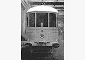
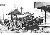
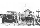
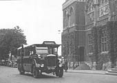
petrol railcars. It was in 1904 that the Company first undertook the design of
a railcar. Two prototypes were supplied to the Great Northern Railway
(GNR) for use on the Hatfield to Hertford branch line (see image 'misc_railcar335'). They were designed to seat 28
persons and were smartly finished in Teak with white upper panels. Propulsion
was provided by twin 38 hp. 4-cylinder, Daimler, side valve engines, with
direct drive via a gearbox, and bevel gearing on to each axle. Being of short
wheelbase and having a very simple suspension, they were rather hard riding and
this led to difficulties with the final drive.
Oliver Bulleid, who was apprentice with the GNR at this
time, was made responsible for maintenance and operation of them, and despite
his love of steam became convinced that petrol driven cars should have been
developed as a substitute for steam on some branch lines. The experiment was
eventually dropped after the cars had run for some months in actual service,
and presumably scrapped, as no further record remains of their continued
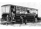
development. A photograph taken at the time shows a group of GNR and Daimler
officials posed with one of the vehicles; it is possible that Oliver Bulleid is
one of this group. Nothing further was done until 1910 when the Company
produced the K.P.L. bus, the design of which was well ahead of its time. The
initials stood for Knight (engine), Pieper (Belgian designed transmission) and
Lanchester (worm drive and suspension). It was experience with this
transmission that prompted them to reconsider the idea of producing a
railcar.
Designs were prepared in 1911-12 for both 3 foot and 3 foot
6 inch gauge railcars, 48 feet long having a single engine with a divided drive
to two four-wheeled bogies. It is not known if these designs were produced with
any specific railway in mind, but in 1912 an enquiry was received from Rhodesia
Railways for four petrol railcars. It was probably this enquiry and the
knowledge that the 'Societe Nationale des Chemins de Fer Vicinaux
Beiges' in Belgium were developing a railcar with the Pieper transmission
that decided the Company to produce a prototype. This was designed for standard
gauge, and the result was a very interesting and handsome vehicle.
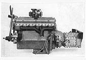
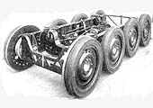
The chassis was of simple braced channel construction
carrying two 105 hp Daimler sleeve-valve engines, each, with its own dynamotor
located on either side of the car. Transmission was through two universally
jointed shafts and worm gearing on to the inside axles of the four-wheeled
bogies. A magnetic clutch and transmission brake formed part of the power unit.
In normal running the two engines drove while the dynamotors were charging the
accumulators. When extra output was required the accumulators automatically
came into action to drive the dynamotors which thus became motors in their own
right and provided an increase in available power. In the event of an engine
failure, the railcar could still be driven home.
Compressed air brakes were fitted, and carriage heating
provided by hot water radiators in circuit with the engine cooling system. The
body, designed to seat 60, was built by Metropolitan Amalgamated Railway
Carriage and Wagon Company Ltd (later to become Metropolitan Cammell after the
company took over the rolling stock arm of Cammell Laird) and was of steel
panel construction on an ash frame. The makers plate gives the date as 1912,
but it was 1913 before this was delivered to the Daimler Works at Coventry. The
tare weight of the finished vehicle was given as 77,000 lb. First tests took
place in 1914, but the war brought all development to a halt as the factory was
turned over to the production of munitions. It was March 1918 before extensive
testing under service conditions recommenced. These were undertaken in
conjunction with the LNWR. Mr Dingley, Chief Assistant to Bowen-Cooke, and Mr
Morris, Chief Assistant to the electrical engineer were delegated by that
Company, while Mr Balcombe and Mr Barriman represented Daimler. The LNWR
stipulated certain minor alterations, inspection panels, removable driver's
seats, engine indicators, interior layout and colour scheme, which was French
grey lined out in white with a thin maroon line in the centre. No lettering or
numbering was decided upon. The regular route selected for testing was from
Daimler Halt, where the car was normally kept, Nuneaton, Rugby (on the main
line), Northampton, via Market Harborough and returning via Rugby, Leamington,
Kenilworth and Coventry. Tests went on throughout 1919 and a report dated March
3 shows that it was capable of 70 mph on the level, and at 50 mph petrol
consumption was 4.5 gallons per hour. It was possible to maintain this speed
with one engine on idle. Maximum engine output recorded at 70 mph was 125
bhp.
Despite successful trials, the LNWR had lost interest in the
railcar by February 1920 and the testing was discontinued. Although other
companies, notably the Dublin and South Eastern Railway, who offered to
purchase the vehicle if Daimler would undertake to alter the gauge to 5 ft 3
in, showed interest, the car remained in the works siding until the middle of
1921 when the decision was taken to abandon the development altogether. Dr
Frederick Lanchester writing to Percy Martin referred to the enterprise as
'a successful but commercially unpromising mechanical frolic.' One
cannot help reflecting though that, had the Company's interests at that time
been less diversified, and the railcar been given a more enthusiastic and
extensive development, the result would have been commercially successful, and
may well have changed the later development of the Company.
We would like to express our thanks to Roger Wyatt of
the South Australian Protofour Group for his assistance in obtaining a copy of
the Model Railway News article.
back to
top
Michelin railcars
Darren Kitson
La Micheline, in English The Michelin, was the name
applied to a series of railcars running on Michelin pneumatic tyres. The name
seems to have applied more specifically to earlier types which resembled road
lorries in both rigid and articulated form. Apart from initial experiments,
such as that described below, the railcars were not converted road vehicles.
Nor were they diesel railcars as some sources claim, they were petrol railcars.
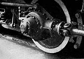
The principle was pneumatic tyres mounted on wheels similar to those of road
vehicles but bolted onto a steel disc which served as a flange. Thus the
railcars offered smooth and near-silent operation with the added benefits of
better acceleration and braking, due to the better grip offered by rubber, when
compared to conventional steel railway wheels. The idea is credited to Monsieur
Edouard Michelin who, it was said, had problems sleeping on overnight trains
due to track noise. Standard railway vehicles are far too heavy for pneumatic
tyres, however, so Michelin realised the way forward was with lightweight
railcars. To this end, a standard Renault car was converted during 1929.
The Paris - Lyon - Mediterranee Railway (PLM) was approached
regarding trials, after the converted Renault had operated successfully in the
Michelin works sidings at Clermont - Ferrand. The PLM, having composed itself
following a mixture of horror and hysterics, agreed to trials on an isolated
branch line in the Savoy Alps with a breakdown train in attendance. The latter
transpired to be unnecessary and the trials were a total success to,
apparently, the surprise of all concerned. It has to be said that credit must
be given to the Michelin company for by 1931 they had produced an 18-seat
railcar which was demonstrated, successfully by all accounts, between Paris and
Deauville during that year.
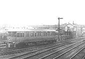
By 1932 Michelin's Type 9 railcar had appeared and in that
same year one of these was sent to Britain for trials. We know from surviving
records that the railcar was in Britain by February 1932. The Type 9 railcar is
known to have also operated in the Leamington Spa area and between Oxford
(Rewley Road) and Bletchley. The railcar was articulated with a six-wheel bogie
at the front and, despite appearances, a four-wheel bogie at the rear (earlier
examples had a single axle at the rear). Brakes were Lockheed hydraulic, acting
upon all wheels.
The power unit was constructed by Renault and the engine was
a Panhard - Levassor sleeve valve petrol unit of 27 h.p. This figure was the
RAC rating; a peculiar system devised by the RAC on behalf of the British
government for taxation purposes. The calculation took into account only the
cylinder bore diameter, not the swept volume of the pistons. The actual brake
horsepower of this railcar engine would have been in the region of 80 - 85 h.p.
at 2,500 - 3,000 r.p.m. Petrol engines were used because no diesel engine
available at that time had a suitable power-to-weight ratio; in other words the
then-available diesel engines were too heavy. Sleeve valve engines are today
museum pieces. The inlet and exhaust ports were controlled by cylindrical
sleeves inside the cylinder bores and which moved up and down by means of cams.
The best known names associated with sleeve-valve engines were Ricardo and
Knight, the latter design being used by Daimler in its 'Silent Knight' engine.
These engines, at the time, offered a number of advantages over other types but
their oil consumption was necessarily heavy and vehicles so fitted were
characterised by the haze of blue smoke which followed them everywhere they
went.
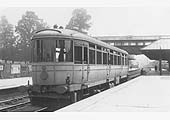
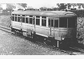
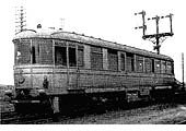
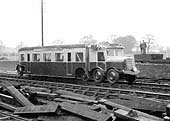
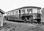
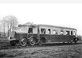
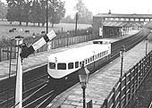
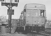
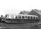
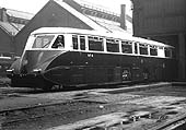
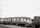
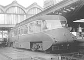
The two images of the railcar in what is thought to be a
factory siding in Coventry ('lnwrcov3749'
and 'lnwrcov3763') show a board at
cantrail level with just the name 'Michelin' displayed. However, the
image of the railcar at Widney Manor ('gwrdm421') has a longer board, again at cantrail
level, with the legend 'Running on Michelin Pneumatic Tyres' displayed.
The radiator grille was a dummy; aircraft type radiators being fitted one each
side of the cab roof. This in turn meant topping up of the coolant had to be
done via a filler cap located on the cab roof. A four-speed manual gearbox was
fitted and, with the obvious omission of steering gear, the driving controls
were the same as those of contemporary road vehicles. A separate reverse
gearbox was fitted to allow all four speeds of the main gearbox to be used when
running in either direction and this bi-directional ability was the reason for
the use of aircraft type radiators. Drive, it is believed, was from the engine
to the centre axle with a roller chain connecting to the front axle with
remaining axles therefore being purely load-bearing.
Given that a separate reverse gearbox was fitted but that
the cab and controls were otherwise similar to a road vehicle, quite how these
railcars were driven in reverse is something of a mystery. A surviving French
document suggests these railcars needed turning at the end of each trip, but
some details of the rear end of the Type 9 are known.The body sides tapered
inwards and the roof downwards to meet a door in the end of the body. In the
upper part of the door was a two-piece window, the top section of which appears
to have been hinged from the top. This top section had a windscreen wiper. On
the left side of the body's rear end was a klaxon and on the right side a
single headlamp. These items strongly suggest driving controls were fitted at
the rear but bearing in mind the road vehicle type cab and controls at the
other end, plus the articulation, quite what the precise arrangement was is
difficult to comprehend. Also, driving controls immediately behind an opening
door somehow seems rather unlikely.
The passenger section of the Type 9 was a rudimentary
affair; it consisted of a welded steel frame covered in canvas - presumably
doped (a form of varnish) as in aircraft practice. Seating was for just 24
passengers, while heating was achieved by the simple expedient of passing air
over the engine exhaust pipe. The railcar weighed, in working order, a mere 5
tons and was capable of speeds in excess of 60mph. The lightweight construction
was necessary due to the inability of the pneumatic tyres of the time to
support the heavier loads usually associated with railway vehicles.
Tyre-to-rail contact area was, of course, dictated by the width of the rail
head, so to have wider tyres would have been pointless. It was for these
reasons the railcars, once out of the early prototype stage, had 8, 10 and
eventually 16 wheels. Tyre pressure is unclear, with accounts varying between
'low pressure' and 85psi. In the event of a puncture or loss of pressure, by 15
p.s.i., for other reasons, a warning horn would sound in the driving cab and
pressure gauges were fitted to each wheel. If a puncture occurred the Type 9
had a wooden rim inside the tyre which prevented total collapse. Later railcars
had steel rims inside the tyres while the Coventry railcars had solid rubber
tyres within the pneumatic tyres. Changing a wheel was accomplished in exactly
the same way as on a road vehicle with spare wheels, jacks and other tools
being carried.
On plain track, tyre wear was said to be negligible but
points and crossovers took their toll of the tyres. Michelin themselves stated
their 'Super Low Pressure' tyre had a service life of over 18,500 miles while
other sources state the tyres were good for an average of 20,000 miles. Such a
mileage was good by the road vehicle standards of the time but the greater
mileages railway passenger vehicles are expected to achieve meant tyre changing
would have been necessary at frequent intervals. Even a passenger train, or
railcar, operating only branch and local services would be expected to cover,
on average, 2,000 miles per week, so tyre replacement would be required every
nine or ten weeks. However, we must be careful not to judge too harshly the
engineering standards and expectations of almost a century ago with those of
today.
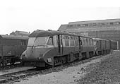
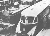
The view of the Michelin Type 9 railcar's rear end (see
image lnwrcov3749), is said to have been
taken in April 1932. As stated in the caption, visible are the klaxon horn,
single headlamp and windscreen wiper on the end door. Despite these
embellishments it remains difficult to see how these railcars could be driven
from the rear. Was there really linkage to the road vehicle type controls at
the other end? Was there really a driving position behind the opening end door?
These are questions to which answers have proved evasive. The large disc on the
near mudguard/splasher presumably deputises for a tail lamp. It is not known
what the cranked bar apparently protruding from the rear of the vehicle is.
This view gives an idea of the construction of the passenger section of these
contraptions. Bearing in mind the body was of doped canvas on a lightweight
tubular frame, the passenger section was little more than a tent on wheels.
Crash Worthiness? Minus ten perhaps!
The Type 9 was returned to France at an unknown date towards
the end of 1932 or in early 1933. At this point there is some confusion over
what happened next. Two photographs exist of a Type 11 railcar; one taken at
Leamington Spa* and the other at Harwich, with the latter taken just
after the railcar had been unloaded from the Dunkirk ferry. The Type 9 entered
Britain via Tilbury and a check on freight train ferries at that time shows the
port had indeed changed from Tilbury to Harwich during 1933. Therefore we know
the Type 11 railcar entered Britain no earlier than 1933, so it is quite likely
the Type 11 was sent from France as a swap for the Type 9 which had arrived the
previous year. Whilst similar to the Type 9, the Type 11 had a few differences;
a more powerful engine was installed; the cab differed in detail and an
all-over livery was applied (possibly a deep shade of red). There was also the
addition of the tubular object on the cab roof; this was in fact a header tank
for the engine cooling system and topping-up was achieved by removing a cap of
which there was one at each end of the tank. Little is known of the Type 11s
time in Britain, but it appears not to have been tested on the Southern Railway
but instead pottered around the Leamington Spa area and the Oxford - Bletchley
line much the same as the Type 9 had later done. There is some very scant
evidence that it made one trial run to Cambridge. The Type 11 returned to
France after a very short stay in Britain. Tyre size was 910mm x 125mm and this
seems to have been consistent for all standard gauge Michelin railcars.
On 16th February 1932 the Commercial Motor magazine
published an article on the Type 9 railcar. While such articles are now a
valuable historical record, the Commercial Motor article, in typical
journalistic fashion, is rather dubious in respect of accuracy. It was claimed
the railcar whizzed along the Oxford - Bletchley line at 92mph fully loaded;
whilst that figure is specific rather than given as, say, 'around 90mph' which
would suggest guesswork, it is doubtful the Type 9 could attain such a speed;
55 - 60mph being the usually quoted figure. The article also states the railcar
was suitable for 'oil or electric' propulsion. 'Oil engine' is a now somewhat
archaic term for a diesel engine and as we have seen it was not possible at
that time to equip these railcars with diesel engines. Nevertheless even today
some people, who in many cases ought to know better, still describe these
railcars as 'diesel'. Electric propulsion was also a somewhat ridiculous claim
as rubber tyres would not provide the current return path necessary with
overhead wire or conductor rail power supplies. Battery power would in theory
have been possible but the ever-present problem of battery weight would have
made it completely impractical for the Michelin railcars which through
necessity had to be lightweight.
Darren Kitson
* A copy of this photograph would be very much
appreciated
Film of the Experimental Michelin Rail Cars in action
 |
French streamlined rail
car
On the LMS rail track between Leighton Buzzard,
Bedfordshire and Euston, London. Originally part of the film 'New in a
Nutshell'. |
|
Michelin auto-trein
(1932)
The Michelin Rail Car performing on Dutch Tracks. Its
similar to that trialled in the UK. |
back to
top
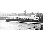
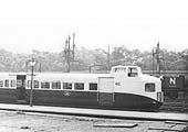
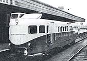
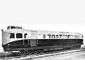
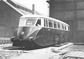
The Coventry Pneumatic Rail Cars
Darren Kitson
The Coventry Pneumatic Rail-cars (see image 'lnwrlave1349') were a development of the
Michelin Types 9, first seen in the UK in 1932, and the Michelin Type 11 first
seen in 1933. Promoted by Armstrong Siddeley, they bore more than a passing
resemblance to the Michelin Type 22 which
was also sent over from France in 1934 and was still evident in
Cambridge in 1935. This shuttling of
railcars back and forth suggests Michelin was keen to ensure Britain's railways
were kept up to date with their developments. The Type 22 railcar was in
outline very different to the Michelin Type 9 and 11 articulated railcars, but
as stated above, very similar at first glance to the Coventry Rail Cars. There
were however a number of differences between them and the Coventry railcars, as
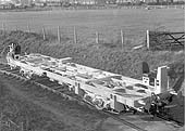
we will see in due course. The French Type 22 was a 56-seat railcar carried on
two 8-wheel bogies and powered by a Hispano-Suiza 240 hp petrol engine. Two
spare wheels and what is assumed to be a toolbox can be seen underneath the end
of the body. Passenger access was via a single-leaf air-operated sliding door
on each side of the body in the centre. A toilet compartment was provided and
at the powered (No 1) end was a luggage compartment accessed by roller-shutter
doors. Braking was air-assisted hydraulic, acting on all wheels.
Hispano-Suiza was a Barcelona based company with tentacles
in France and better known for their large, upmarket cars and their involvement
in the aircraft industry. The company still exists but is, at the time of
writing, known as Safran following a series of takeovers and mergers. For use
in the Michelin railcars, Hispano-Suiza developed a lightweight and rather neat
engine known as the Type 86. It was a 12 cylinder horizontally-opposed unit
using much aluminium alloy in its construction and designed to sit transversely
in the bogie frame, drive to the wheels being via fluid coupling and
self-changing gearbox to one axle and thence via roller-chain to an adjacent
axle.
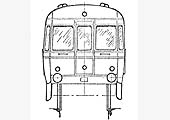
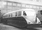
Perhaps the most striking feature of both the Type 22 and
Coventry railcars was the 'conning tower' and its driving position. This meant
only one driving position, and thus one set of controls, was necessary. The
drawback with this arrangement was the driver needing to turn one way or the
other according to direction of travel. To access his position, the driver had
to first climb onto a raised platform and then onto his seat which was
cantilevered from safety railings around the edge of the platform. The precise
method of control with railcars using the Type 86 engine which, being bogie
mounted, moved relative to the body, is not clear, but other railcars used a
more conventional Hispano-Suizar V12 engine (a bored-out Hispano-Suiza J12
automotive engine) mounted in the body underframe and in these cases
control was via levers projecting up into the conning tower. The official term
for the conning tower seems to have been 'Driver's platform'.
The image of the Cambridge railcar shows the conning tower,
as we will call it, is more or less located along the body centre line.
Railcars using the underframe-mounted V12 engine had, by necessity, the conning
tower located to one side of the body and this was the case with the Coventry
railcars. All the railcars had a radiator mounted in a conventional position,
as per road vehicles, above the frames at the No 1 end. For running with No 2
end leading the radiator had shutters which closed and instead air was drawn in
via roof-mounted scoops. These scoops can be seen either side of the conning
tower in the Cambridge image. The Coventry railcars used a similar arrangement
but which differed in detail. The Coventry cars had 'Coventry Railcar'
monograms on their body sides. The 'Cambridge' Type 22 railcar also had
monograms which appear to have stated 'Pneumatic Railcar' but surviving
photographs are too unclear to be certain.
At around the time the Coventry cars were introduced in
1935, the Type 22 railcar simply disappeared. Probably, the Coventry cars
rendered it redundant and it returned to France. The Coventry Pneumatic Railcar
Company was a joint undertaking between the LMS, Michelin and
Armstrong-Siddeley of Coventry. Like Hispano-Suizar AS was also a producer of
upmarket cars as well as being involved in the aircraft industry. After the
Second World War AS became part of the Bristol-Siddeley-Maybach concern,
producing Maybach engines under licence for some of British Rail's
diesel-hydraulic locomotives.
For the Coventry railcars, Armstrong-Siddeley had developed
their own V12 petrol engine; a 13 litre unit giving 275 hp at 3,000 rpm. It
weighed a mere 1,000 lb and the complete railcars weighed, in working order, a
very commendable 6½ tons. However, a drawing exists clearly intended to
show a Coventry railcar (it is titled as such) and this states the weight in
working order as being a fraction over 8 tons. An Ogden's cigarette card
depicting a Coventry railcar gave the tare weight as 9 tons or 14 tons fully
laden. The drawing also shows the conning tower located just off the centre
line of the car, as per the 'Cambridge' Type 22, and with the roof-mounted air
scoops also as per the Type 22. As pictures of the Coventry railcars show, the
design as-built was rather different and the reasons for the changes are not
known although we can guess they may have been connected with the decision to
use the V12 engine instead of the Hispano-Suiza horizontally opposed unit.
Mentioned earlier was the fitting of solid rubber tyres
within the pneumatic tyres of the Coventry railcars. This allowed the railcars
to continue in service with a punctured tyre until a convenient time to change
the offending wheel arose, although this would presumably have required reduced
speed, inner tubes were also fitted, as was the norm at the time, and this
applied to all the pneumatic railcars. The inner tubes differed to those used
on road vehicles because of the need to accommodate the anti-collapse rims or,
in the case of the Coventry railcars, the inner solid tyres. As far as can be
ascertained regarding the Coventry railcars, the inner tube was of a 'U' cross
section and was fixed and sealed to the wheel rim and with the inner solid tyre
inside the tube and the pneumatic tyre outside. Thus when a puncture occurred,
the inner tube deflated and the railcar ran on the inner solid tyre. This means
air would have provided nothing more than a cushioning layer between inner and
outer tyres - very different indeed to the much simpler system of tubeless
tyres were are familiar with today on road vehicles.
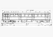
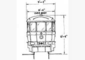
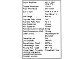
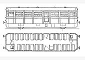
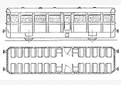
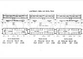
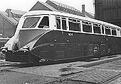
The Coventry railcars were 55 ft long overall, 9ft wide and
12 ft high from rail to top of conning tower. The conning tower had, of course,
to fit within the British loading gauge and, like the Type 22, the Coventry
railcars had to suit the height of British station platforms. It was for those
reasons the railcar bodies were rather squat, giving the illusion they were
wider than they actually were. For their time and to British eyes, they were
ultra-modern in appearance and their livery, said to have been crimson lake and
a light shade of cream, while not exactly new (the LNWR had used a similar
coaching stock livery) must have been quite eye catching. Coventry No 1 made
its debut on 20th June 1935, with No 2 following soon afterwards. One, at
least, of the Coventry cars is known to have undertaken trial runs between
Rugby and Market Harborough (part of the now-closed Rugby - Seaton - Stamford
Peterborough route) and also between Oxford and Cambridge. Details of the
latter are, however, vague and it is unclear if either Coventry car actually
ran as far east as Cambridge. Most photographs of the Coventry cars depict them
in service in the Coventry, Kenilworth / Leamington Spa area.
No 1 is known to have then made a press run from Rugby to
Wansford (near Peterborough) and return, following which both railcars operated
services in the Coventry - Leamington Spa - Rugby - Nuneaton area. The services
were advertised by handbill and slotted-in between regular timetabled services
operated by proper trains. They were based at Rugby a three road part of the
shed being reserved for them. Possibly this was done partly to keep them away
from steam locomotive grime but mainly to keep the fuel supply petrol, away
from the risk of fire. In time, the Armstrong Siddeley engines became
problematic and at least one railcar was given a Hispano-Suiza engine instead.
This was presumably a J12 as fitted to the later Michelin railcars.
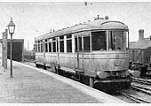
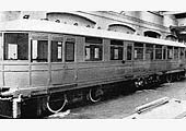
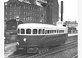
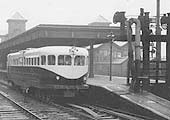
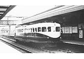
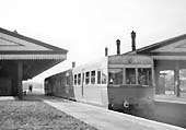
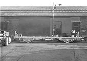
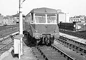
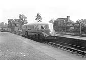
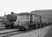
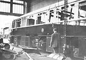
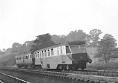
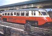
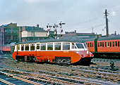
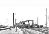
Image 'lnwrlave3766'
shows Coventry Pneumatic Rail Car from the rear, in this case the driver's end,
but with the vehicle be propelled forward. The side position of the conning
tower can be seen, this being necessary because of the underframe-mounted VI2
engine. The exhaust silencers can be seen, as they can in the previous image;
there was one for each bank of cylinders and located conspicuously but neatly
under each side of No 1 end. Another difference to the Michelin Type 22 was the
two-leaf sliding passenger doors mounted externally of the body. The oil tail
lamp was a mandatory requirement despite these railcars being fitted with
electric lighting clusters. Mentioned earlier was the air scoop arrangement
which differed to that of the Type 22. The scoop was raised and the radiator
shutters were closed when the railcars ran with No 2 end leading. With No 1 end
leading the radiator shutters opened and the scoop closed. When closed, the
scoop was flush with the roof. There has been some suggestion that in the
Coventry' cars the driver was able to sit actually facing the direction of
travel and this does appear to be the case from photographs of the cars in
service. If so, the arrangement of the driving seat and controls has to be
questioned but details are not known.
The railcars were popular with the travelling public and:
providing it wasn't a hot day, with the crews too. The railway authorities,
however, quickly lost interest and the scheme was abandoned in 1937. Later that
year the Coventry' railcars were taken to the Michelin premises at
Stoke-on-Trent and there they lingered until 1945 when they were scrapped. All
that remains of them is one wheel, in the National Railway Museum having been
presented by Michelin. All the lightweight pneumatic railcars had their
drawbacks. The necessary light weight prevented the use of proper buffing and
drawgear; their near-silent operation was seen as a hazard to track workers
used to the sound of steam locomotives and the rubber tyres could not operate
track circuits (track circuiting is a system whereby a small electric
current is passed through the rails and when this is short-circuited by
conventional steel wheels the instruments in signal boxes are actuated).
The Coventry railcars were fitted with skates to eliminate this problem but
apparently they proved unreliable). One perpetual problem with any lightweight
railway vehicle is the relatively high cost of construction and of repairs
following accident damage; British Railways was mindful of this problem many
years later with their Wickham-built diesel multiple units and railbuses.
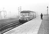
It is said that the Coventry railcars were prohibited from
running during the hours of darkness and during fog due to safety concerns. The
hours of darkness were, of course, known in advance and as the railcars were
not guaranteed to run this would not have caused any problems. Fog, however, is
less predictable so must have caused some cancellations at short notice. It is
not known if these restrictions applied only to the Coventry railcars or all
those which operated in Britain but it is likely it was all of them. Another
aspect for which the answer is not known is whether the safety- concerns were
genuine or part of an attempt by a disinterested LMS to kill off the project,
but given that the railcars were quiet running and very dodgy where track
circuits were concerned we can probably safely assume the concerns were
genuine.
Despite the drawbacks the railway authorities in Britain
were quick to point out, the main reason for their demise in Britain was
probably the Second World War. As war clouds gathered, industry, including
Armstrong Siddeley, was gearing up to rearmament and other war production and,
as happened with the LMS articulated diesel multiple unit, experimental
projects were very' much pushed into the background. The success of the Great
Western's AEC diesel railcars may also have influenced the decision to abandon
the concept.
Drawbacks or no drawbacks, war or no war, the French, as
might be expected, took a totally different approach and over one hundred
Michelin railcars gave many years of good service in France and her colonies.
Others eventually found their way to other parts of the world and in the USA
the Budd company produced them under licence. Today several examples can be
seen in museums while at least one, in Madagascar, is still operational as of
2015. On a brighter note, several Metro systems operate rubber-tyred trains.
Paris, Mexico City and Santiago have some lines operated in this manner while
the Montreal Metro is currently operated entirely by rubber-tyred trains. The
rubber-tyre principle offers distinct advantages in urban areas, especially
where lines are underground, where reduced noise and vibration are most
desirable. Metro systems are also usually self contained and operate,
engineering trains excepted, only passenger trains of lightweight fixed
formation stock, therefore the problems of operating rubber-tyred trains on
main lines where they have to integrate with conventional rolling stock are
eliminated. However, while the rubber tyre principle remains on these modern
metro systems, the precise technology is a long way from the Michelin railcars
of yesteryear.
Darren Kitson
Operational Trials
Pre production views and design specifications
back
to top
The LMS Ro-Railer
The following article appeared in Railway Wonders of the
World published on 21st June 1935. Darren Kitson provides a word warning when
using archived material from such sources. He points out that most articles are
not objective assessments of the item being reviewed as they are often
published at the time of their launch and consequently the claims of
achievements and benefits are provided unchalleged by the relevant PR
department.
COACHES FOR ROAD OR RAIL
Experimental Services Designed to Speed-up Travel
Introduction
If a broad view is taken of the transport conditions of most
civilized countries having the usual road and railway facilities, it must be
agreed that the road motor vehicle, whether it is used for passenger carrying
or for goods conveyance, has some definite advantages over the rail vehicle. It
is not limited to a single track between two fixed stations. The motor vehicle
can carry its loads over a network of roads from door to door, without the
necessity of transhipment. Further, its use is generally independent of any
other ordinary road traffic, and it can start at any convenient time without
affecting other road services. The railway goods or passenger vehicle, on the
other hand, must keep to its own track and also to a timetable arranged to keep
the track clear at certain specified times only. Moreover, the railway station
or goods depot is often a considerable distance from the destination of the
passenger or goods, and some supplementary form of transport becomes necessary.
With goods traffic, the usual procedure is to load the goods intended for
transit on to a motor lorry, convey these to the railway depot, and unload them
on to the railway trucks or vans. After reaching the nearest station or depot
on the railway line the goods must be unloaded from the railroad on to another
motor vehicle, conveyed along the roads to their destination and then unloaded
once more This method of goods conveyance not only involves an appreciable loss
of time in transit, but also necessitates two loadings and unloadings, with the
added risk ot damage during these processes ; moreover, it necessarily adds to
the cost of transport.
In view of these disadvantages it might be thought that to
use the railway at all is a doubtful policy where small quantities of freight
of, say, two to four tons are concerned, when the goods could be conveyed from
door to door without employing the railway. The answer to this is that in
partly developed districts, and in areas where the roads are either bad or are
congested, it is very much quicker to send goods by rail. The speeds employed
on railways are normally much higher than those on the roads. For long distance
work, also, the advantages of rail transit are indisputable ; moreover, the
transit costs are lower. In many undeveloped or partly developed countries
there is generally a railway joining the main towns or industrial areas, and a
network of roads leading to the railway stations and depots but there are few
long distance main roads And it is here that the railway scores over the road
vehicle ; for the latter cannot be used without suitable roads. From these
considerations it seems that in its own sphere of operation the motor road
vehicle and the railway vehicle each possesses definite advantages.
With a knowledge of these facts it is not surprising that
transport engineers have considered the possibility of designing a new type of
vehicle that will combine the advantages of each type while avoiding its
drawbacks. After a careful study of this problem, combined with a good deal of
research work, a suitable vehicle, known as a "road-railer," has been evolved.
This can run equally well on either the road or the railway track. It can thus
begin its journey by road from the loading place to the nearest railway
station, and then transfer to the railway lines, becoming for the being a
rail-coach. At the end of its railway journey it is once again transferred from
the railway track to the road and thence driven off, just as any other motor
vehicle, to its destination. It may be of interest to point out some of the
more important uses of this combination vehicle. Its particular application is
on branch lines and, especially, on those branch lines where towns and villages
lie some distance from the railway. Passengers or goods may be taken on at any
convenient place, wherever there is a suitable road. New or partly developed
districts lying some distance from the railway can thus benefit materially from
the use of the road-railer. Further, the possibility of using this vehicle for
week-end and other abnormal traffic must not be overlooked. Road congestion,
leading to both slow and dangerous travel, has often created a problem which
this new type of vehicle at once solves. Both types of vehicle-passenger and
goods-can be attached to trains, with the added advantage that they can be
detached when required to proceed to their destinations as ordinary road
vehicles.
Apart from its advantages to the railway authorities, the
road-railer may be used in various Government services. Its utility in
countries where, during certain periods of the year, the rains are so heavy
that the roads become impassable, will undoubtedly be recognized, for it will
then be possible for journeys to be made over the permanent way. On the other
hand, should a portion of the track be destroyed, or under repair, it is then
possible to divert the road-railer on to the road and return it later to the
track at the other side of the part which is out of commission. It may even be
an advantage to use the vehicle over long distances by rail, and then to cut
across country and afterwards connect up with another railway, without having
to unload and transfer the goods, as must be done with conventional vehicles.
Perhaps the greatest advantage of the road-railer for use in developed
countries, such as Great Britain, is the rapidity and economy with which
passengers and goods can be transported over medium and longer distances, from
sources and to destinations remote from the railway station.
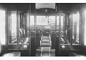
From the point of view of the passenger service, the low
tractive effort necessary to propel the vehicle on the rail results in much
lower running costs, due to the reduced fuel consumption and absence of
pneumatic tyre wear ; this should involve lower passenger fares. Again, when on
the railway track the road-railer is capable of travelling, with safety, at
higher speeds than it can attain on the roads ; thus, with the Karrier
road-railer speeds up to sixty miles an hour are well within the engine's
capacity. Further, it is much safer and easier to drive a road-railer on the
railway lines than on the roads, for there are practically no obstructions on
railway lines. From the point of view of the passenger's comfort, the
road-railer has the advantage, well-known to users of motor-coaches, of
combining first-class seating with third-class fares. Again, where the railway
is the shorter distance between two towns, a certain amount of time is saved.
As a goods vehicle the road-railer not only avoids duplicate loading and
unloading, but also, owing to the lower fuel costs on the railway track, and to
the absence of tyre wear, proves to be more economical than other types of road
vehicles.
The LMS Karrier Road-Railer
The various advantages outlined above are embodied in the
Karrier road-railer about to be described. This vehicle represents the results
of over two years' experimental work. The first production model was delivered
to the London, Midland and Scottish Railway. It was in the form of a twenty-six
seat passenger coach, and complied with the Ministry of Transport's
Regulations, as well as those of the railway authorities. Large capacity
double-deck passenger vehicles can also be built. The range of road-railer
freighters is from 30 cwt. to 8 tons, if complying with the Ministry of
Transport's Regulations, but for service abroad they are available from 30 cwt.
to 20 tons. The vehicle which ran experimentally on the LMS. is fitted with a
six-cylinder petrol engine of the usual commercial motor-vehicle design, rated
at 37.2 hp, It has a wheel-base of 17 feet 1 inch, and road wheel track of 6
feet 3½ inch The rail track is the standard 4 feet 8½ in. gauge.
The transmission has a top-gear ratio of 7 to 1 for road use, and 4.2 to 1 for
the railway track. These ratios give maximum speeds on the road and rail of 60
and 75 m.p.h., respectively. The petrol consumption on the road is 8 miles per
gallon ; on the railway track it is 16 miles per gallon. The total weight of
the vehicle, unloaded, is 7 tons 2 cwts ; 3 tons are allowed for the weight of
the passengers, staff, and luggage.
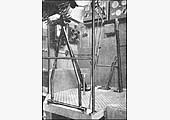
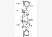
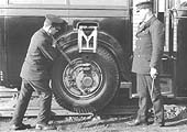
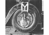
The following is the method employed in this ingenious car
for converting the wheels from the pneumatic road type to the steel-flanged
railway pattern. Flanged rail wheels are fitted to the vehicle's axles ; on the
outside of these are placed pneumatic-tyred road wheels, each of which is
mounted on eccentrics fitted to an axle extension through the rail wheel. When
on the road, the road wheels are locked concentrically to the rail wheels,
which, being of smaller diameter, are quite clear of the road. The wheel
changing operation is as follows. For road to rail transference, the
"road-railer" is driven on to the rails at any place where the road has been
made up level to the rail tops. Then, with the rail wheels directly over the
lines, it is driven forward a few yards until it reaches a point where the
made-up road is tapered off. The rail wheels now gradually come into contact
with the rails, and take the weight of the machine off its road wheels. The
road wheels, which are mounted on an eccentric device, are then raised above
rail level by the action of the driver, who rotates them on their eccentrics
and locks them to the chassis frame by means of a pin. The road wheels,
therefore, do not rotate when the vehicle is moving on the rails. The
"change-over" operation is, of course, reversed when returning to the road.
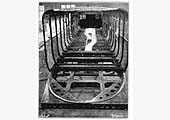
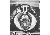
The same principle holds good for both the front and rear
wheels of the vehicle. The components are generally interchangeable on all four
wheels. Two eccentrics per wheel are employed in this particular design, which
enables as much lift to be obtained as is allowable by the wheel rim diameter.
The operation of lifting a wheel of the necessary dimensions requires little
manual effort. Further, when the road wheel is in a lifted position there is
only one bearing in the mechanism which possesses any velocity relative to the
main hub. In other words, all the road wheel mechanism remains stationary while
the road wheel is out of action. The rear wheels are driven by a propeller
shaft in the same way as an orthodox road vehicle, and the drive is cut off
from the road wheels by disconnecting two pins which are utilized to secure the
road wheels in an eccentric position to the slipper block structure. This
structure-one for each wheel-is a device which provides support for the road
wheels in their raised position while permitting vertical relative movement
between the axle and the frame when the vehicle is on the rail. The structure
is hinged in two places, and folds into the body when the vehicle is used on
the road. It also offers, due to its radius from the centre of the axle, the
required resistance to overcome the static friction between the wheel hub and
the inner eccentric bearing. There is no load either on this slipper block
structure or on the pins, except that immediately required to overcome static
friction between the inner bearing of the inner eccentric and the driving hub
when beginning to move on the rail. The pins, however, are of ample dimensions,
for they are the medium through which the road wheel drive is taken when the
vehicle is running on the road.
It is impossible to insert these pins in the wrong position
when raising the road wheels, as the horn block slipper covers up the driving
pin hole which is not required and exposes the one into which the pin is to be
inserted. The construction of the horn block slipper is unique. It has in its
body an automatic lock which prevents the pins from becoming loose when any
small vibration is experienced. While this object is satisfactorily achieved,
the construction is such that with a minimum of effort, applied sharply, these
pins may easily be withdrawn. A similar device is incorporated on the driving
hub flange when the pins are inserted for road work. Very long pins ensure that
the drive is distributed over wide centres, and their diameter is such as to
render wear on the pin bearings highly improbable, on account of the small
intensity of pressure to which they will be subjected. When the road wheels are
driving, the rail wheels also are revolving, the connection being made through
the outer portion of the hub end which is keyed on a taper to form a connection
between the hub and the driving wheel. The wheel bearings are of the adjustable
taper roller type. Another interesting feature is the adoption of the
Lang-pattern laminated wood wheel, which possesses both resilience and
exceptional strength, and assists greatly in the elimination of track noise.
Detachable and renewable steel tyres are employed on these wheels.
As the vehicle runs up to the rail it is impossible to
guarantee the position that the driving pins of the road wheel will occupy in
relation to the holes in the slipper block. Provision is therefore made whereby
the inner eccentric may be positioned in relation to the slipper block. Having
established this position it then becomes necessary to ensure the correct
relationship between the inner and outer eccentrics. For this reason two slots
are provided in the inner eccentric into which the single plunger may operate.
After the position of the inner eccentric is located the wheel may be swung
round the periphery of that portion of the mechanism. And, when the outer
eccentric has assumed its correct radial position in relation to the inner
eccentric, the plunger, which has previously been withdrawn automatically from
its original slot, now becomes engaged with. a slot. This slot has been
correctly positioned by its relation with the lower slipper-block pin. This
ensures that the two pin holes are in line one with the other, and also in a
correct relationship with the holes in the slipper block. It will be seen,
therefore, that it is impossible to swing the outer eccentric past its correct
centre. The condition is now one in which the inner eccentric is prevented from
rotating by the lower pin, while rotational movement of the outer eccentric is
also prevented by the upper pin and the spring plunger. It should be made
perfectly clear, however, that the two pins substituted in the slipper block
are in a position which definitely has disconnected all the drive from the hub
to the road wheel of the vehicle in question.
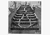
The chassis of the road-railer generally follows
conventional commercial vehicle practice. The gear-box, however, is provided
with an additional over-speed arrangement to permit of a higher top gear (4.2
to 1), when travelling on the railway, than that used on the road (7 to 1). The
braking system serves equally well for both road and rail operation ; on the
railway, of course no skidding is possible when the brakes are applied. The
vehicle may be stopped in a very short distance from speeds of forty to fifty
miles an hour without the danger of wheel-lock. The tractive effort is ample,
and permits the towing of other vehicles. The rear rail wheels are provided
with sanding gear. Buffers are provided at both front and rear, special
supports for these being anchored to the main chassis frame. There is also a
spare wheel carrier fitted at the rear of the chassis. This is mounted on
rollers, and it slides automatically to the ground upon release of the
attachment fittings. Automatic lubrication is arranged for all the working
members of the chassis.
The LMS Ro-Railer
The following article was originally published in Stratford
upon Avon Transport Notes - Volume 02/04 by J R Jennings SMJR line
archivist
I have been researching and lecturing on the Stratford upon
Avon and Midland Junction Railway for over forty years. It is incredible how
many times I am asked about the “Ro-Railer”. This vehicle only served
in revenue service for a few weeks. It has taken on almost mythical status and
although it deserves a place in history its main contribution to Stratford is
that it put the station at Old Town and the LMS railway as an alternative route
clearly in front of a much wider public than it had ever previously enjoyed.
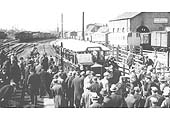
Not since the days of the “Harvard” special trains in the pre-Great
War era did so many people crowd onto the 'other' Stratford station as on the
morning of 23rd April 1932. I estimate that more photos were taken of the
Ro-Railer (and certainly more survive) than of any other ex-SMJR line subject.
If only the unique Fairlie engine had enjoyed similar status! This short volume
has been edited over the years as new data has come to light. It draws together
information that appears in many sources elsewhere.
The Stratford upon Avon and Midland Junction Railway and the
LMS Railway that took it over in 1923 made various attempts over the years to
offer a through connection between Stratford and London. The rival GWR route
with a change at Leamington Spa was longer than either the Stratford -
Marylebone or Stratford - Euston possibilities that existed using the SMJ
route. In the early 1900s a through service was provided by a coach that was
worked over the SMJ line before being attached to a Great Central Railway
London service at Woodford. This involved the coach being 'trip worked' from
Byfield to Woodford and back. Its progress over the SMJ line to Stratford was
slow because it was attached to a normal all stations stopping train. The
Railway 'grouping' of 1923 put the Great Central Railway in the LNER camp with
the SMJ becoming part of the LMSR. This really ended any future cooperation on
through coaches via Woodford. The 'gateway' from the SMJ line to London had
always been via Woodford because when the GCR London extension was built the
need to generate traffic was paramount and the layout at Woodford took account
of interchange traffic with the SMJR. The LMS could direct traffic to its West
Coast Main Line at either Blisworth or Roade. The connection at Roade had never
been fully utilized even for freight but the interchange at Blisworth was one
of the better used parts of the ex SMJ system and although passengers would
need to walk through to the main platforms a reasonable connection to the
capital could be achieved. The authors of the various books on the SMJ have
never effectively explored why the Roade connection was not developed for
passenger through traffic. In mileage terms it was very attractive but the most
plausible explanation is that the LMS (and LNWR before it) did not want to stop
express trains at a relatively unimportant station to attach/detach through
coaches of dubious commercial benefit to them. Some authors have suggested that
the track layout at Roade dating from the 1840s and the lack of a shunting
engine at all times were also considerations.
During the 1920s competition from road transport was
becoming a big problem for all of the railway companies and they explored ways
of cutting costs and developing new traffic on loss making lines. The LMS were
aware that Stratford upon Avon was an increasingly important destination with
the attractions of the 'new' theatre and their own investment in the Welcombe
Hotel. Ways of providing a passenger service of reasonable journey time were
considered and it was decided to trial a new concept of vehicle that could run
on both rail and road. If successful this would have great potential to win
traffic for lightly used lines. In the case of the Stratford service it would
be possible to convey passengers and their luggage directly to and from the
Welcombe Hotel via the SMJ line as far as Blisworth where with just one change
of train they would be conveyed directly to Euston. The journey time would be
enhanced by the vehicle running non-stop from Blisworth to Stratford although
the constraints of a difficult single track line often meant waits at Towcester
and Kineton.
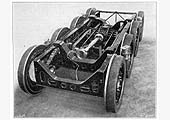
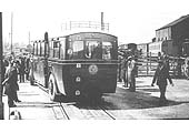
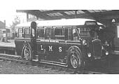
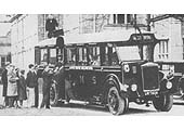
The LMS Ro-Railer UR7924 was ordered by the LMS carriage
division at Wolverton in Feb 1931. The supplier Karrier Motors of Huddersfield
was a surprise to some as they were running down their bus production having
earned a poor reputation for reliability in the 1920s. The chassis was a
standard Karrier Chaser powered by a 6 cylinder engine with a maximum rating of
120hp. The Chaser was the last serious bus design by Karrier. The body was
built by Cravens to their B26C design and featured 14 front facing seats in the
forward vestibule and 12 longitudinal seats in the rear smoking saloon. Luggage
space was provided on the roof or by folding up some of the seats in the rear
vestibule. It weighed 7 tons 2 cwt and was fitted with railway sanding gear,
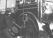
lamp irons and emergency drawgear for locomotive haulage. Loco haulage was
limited to 20 mph although apart from the presumed rescue on its demise there
is no record of loco haulage taking place. The pneumatic road wheels and
traditional flanged rail wheels were mounted on a manually set eccentric
arrangement and could be switched from road to rail in under five minutes by
one man whilst the vehicle stood over a sleepered crossing. The technical
arrangements are dealt with fairly comprehensively in most of the books that
have been published about the ex-SMJR line.
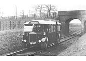
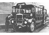
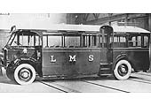
After delivery and acceptance at Wolverton it was put on
trial on the Hemel Hemstead – Harpenden branch where it was photographed
in late 1931 by H C Casserley. In an attempt to gain publicity the LMS decided
to allocate this first experimental vehicle to the ex SMJ section and the
service was launched at Stratford upon Avon on 23rd April 1932. This is an
important day for the town as it is the birthday of William Shakespeare and
there would be many influential people and pressmen around on the day. As
previously mentioned the LMS had converted a mansion at Welcombe into a Hotel
and the Ro-Railer was charged with conveying passengers directly to it without
the need to transfer themselves or their luggage at the railway station. There
was a minor skirmish with an omnibus company who held the local carriage
license and objected to the LMS in effect providing a service on their
territory although they did not offer a route from Stratford LMS to the
Welcombe hotel! This was resolved by the LMS agreeing to charge a flat rate
fare of sixpence (6d) for any intermediate fare stage if passengers were picked
up in the town. There were few takers.
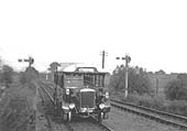
The Ro-Railer suffered from the same problems as many early
road bus conversions to rail in that it was too light for efficient rail
adhesion particularly on a line like the ex SMJ which had the gradient profile
of a switchback. It struggled to maintain progress uphill and was then driven
hard on the downhill to compensate. (The author experienced a very similar
vehicle still in use in Chile in 1993 and the ride qualities were not for the
faint hearted!) The lack of effective suspension and springing meant that the
hammer blow from rail joints and crossings was transmitted to both machinery
and occupants. Early failure of some vital part was inevitable and after a few
weeks of operation the Ro-Railer broke a front axle component whilst in service
near Byfield. It was removed to Wolverton and never used again as a rail
vehicle although the fact that its road registration was renewed for a number
of years after suggests disposal for use as a road vehicle. The LMS did have
plans to order more including goods/passenger convertible versions for branch
line use. These plans were abandoned by virtue of a short minute at an LMS
board meeting in late 1932.
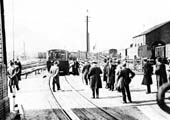
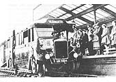
In view of its novelty and the launch on 23rd April there
is a wealth of photographic material of the vehicle. In addition to the railway
coverage the odd shot of it on the streets of Stratford keeps coming to light
as residents come forward with a photograph taken by a relative of this
'unusual vehicle' as the local paper had described it. Apart from Casserley's
efforts not too many photos of it exist outside of the Stratford area or in any
other SMJ l ine station. The launch of the service drew a large gathering of
contemporary railway enthusiasts many of who can be seen in the photographs
that have been well published over the years. Some cine films of the vehicle
have survived and at least one copy is held in the archive collection
administered by Rob Foxon of Leicester.
One Ro-Railer story that has recently surfaced was that it
was alleged to have been sent out to substitute for an unavailable loco and
coach on the Stratford - Broom Junction scheduled service one day. The
turntable at Broom was unavailable (the East to West connection forming a
triangle was 10 years in the future) so the Ro-Railer returned backwards!
The above article was originally published in Stratford
upon Avon Transport Notes -Volume 02/04 by J R Jennings SMJR line
archivist.
The Ro-Railer being presented by Lord Stamp
The Ro-Railer being tested on road and rail
The Ro-Railer's wheel change and technical information
back to
top
British Railways & BTU Experimental Lightweight
Railcars
Stuart Mackay
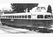
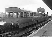
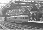
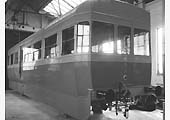
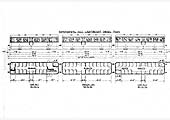
The first three-car unit, comprising cars 1, 2 & 3 was
built as a demonstrator set in 1952 and ran trials on many lines throughout the
UK. It comprised a motor car, a motor brake car and a trailer. It was painted
two-tone grey with red lining but was later purchased by British Railways and
given green livery. Five similar cars were built for BR in 1955 and three more
in 1957, and all eleven spent most of their later lives on the Watford-St
Albans line. They were all withdrawn by 1962. The first three cars in BR livery
can be distinguished by their half-drop windows and lower skirt panels. The
eight later cars had sliding windows and no skirts.
Nicknamed the "flying bricks", a 3-car set was built as a
demonstration train, formed of two power cars and a centre trailer, although it
could also be operated as a one or two car train, The bodies were built by Park
Royal, and the underframe and mechanics by AEC. Initially they were numbered
Cars 1-3, but later given the BR numbers M79740-2. They were trialed in many
places around the country, leading to them being bought by the LMR in January
1955 and a further set and spare power/trailer car delivered in 1955 and
another 3-car in 1957. The later eight cars (M79743-50) didn't have the
bodysides skirts, and had sliding lights rather than droplights on the sides.
They were normally associated with the St Albans - Watford line, and to a
lesser degree the Harrow - Belmont route. Despite the order for more vehicles
they were not successful, and on paper at least some were transferred to the
Civil Engineers Dept. in 1959. Eight vehicles were placed in store at Derby
Friargate mid-1960, the other three still seeing occasional use for a further
year before also going to Derby. They were all cut up by Derby C&W by the
end of 1963.
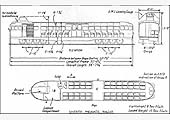
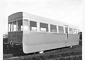
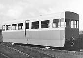
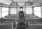
First Three Vehicles
The bodies were designed by BUT but manufactured for them
by Park Royal, and the underframe and mechanics by AEC. Both were ACV
companies. As a 3-car set the length was 120ft 9ins over buffers, weighing
39tons 4cwt. The DMT and DMBT each weighed approximately 15 tons, the TT
weighed 10tons 10cwt. Maximum speed was 45mph. They showed an average fuel
consumption of 11½ to 12mpg per car, or 5¾ to 6mpg for a 2/3 car
set.
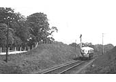
Operations
They ran their first trials between Didcot and Newbury
(DN&S) during w/c 28 Apr 1952. As a demonstration train it was naturally
trialed around many parts of the country. The first demonstration was to
Gerrards Cross, on the 23rd May, and then based on Neasden shed it worked a
series of trials out of Marylebone on outer London suburban routes. Initially
this was on the High Wycombe / Princes Risborough line, working 2 trains each
way daily. Twelve days of demonstration runs in the Birmingham area were
extended an extra fortnight until 12th September 1953. At this time it was
thought that the the BTC would purchase the unit, and after fitting it with
heaters for use during the winter months it would go into regular service
either on the Southminster Branch (ER) or the Watford – St Albans line
(LMR). In late 1953 they were on trial for a short while on the Southern Region
Allhallows-on-Sea branch in Kent, after which they moved back to the London
Midland Region. The Wellingborough to Higham Ferrers branch was another route
the unit was tested on.
Prototype Lightweight railcars in action
Prototype Leightweight railcars being built
Schematic drawings of the Prototype Leightweight
railcars
back to
top
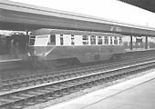
Great Western Railway AEC Diesel Rail Coach
Whilst the Great Western Railway's AEC Diesel Rail Coach was
not initially associated with the county, its development was to prove
beneficial to services originating from or terminating within the county. The
most notable were the Birmingham Snow Hill to Cardiff Central services
commencing 16th July 1934. This service was the first regular diesel working to
be run to a fast schedule in this country and the 117½ miles between
Birmingham and Cardiff were covered in 2 hours 20 minutes and being designed
for express business services they incorporated a buffet bar service. The
interior also had the luxury of removable tables and two toilets. Fares were
charged at the normal 3rd class pricing but bookings were limited by the number
of seats on the railcar. This twice daily working continued in the capable
hands of Numbers 2-4 until 1940.
The following article is produced with the kind
permission of Ruben Grace of www.totally-transport.co.uk
The GWR AEC Railcar
As a large company, the Associated Equipment Co. Ltd, better
known as AEC, owned several smaller businesses. One of these was Hardy
Railmotors, who had already built several small railway shunting engines for
various customers. One of Hardy's employees, C.F Cleaver realised that AEC's
AEC-Ricardo 121BHP 6 cylinder diesel unit, which had already proved its worth
as a reliable and established engine, finding use in many of AEC's bus and
commercial vehicle products, would be perfect for powering a self contained
railcar type unit. The idea was quickly adopted and the first railcar was
broadly based on the Deutsche Bahn's Flying Hamburger, which influenced the
LNER's Sir Nigel Gresley in opting for streamlining on his 'A4' class Pacifics,
in terms of its streamlined body.
However, this all changed following windtunnel testing
carried out by AEC in Chiswick laboratory of the London Passenger Transport
Board which gave the body a more streamlined appearance.The 8.85L, 6 cylinder
diesel engine was mounted vertically and mated to a five Picture speed gearbox
which drove all the wheels on one side of one bogie. This first prototype was
bodied by another of AEC's numerous subsidiary companies, Park Royal, and could
carry upto 69 passengers in style with a driving compartment at both ends of
the vehicle, allowing the engine to be controlled from either end. The wind
tunnel tests had suggested that a streamlined body would reduce fuel
consumption by around twenty percent compared to a normal box shaped train.
However, the engine and Park Royal body combination gave the prototype a poor
power to weight ratio, limiting it to a top speed of 63mph.
Great Publicity
Before the prototype had been finished, the Great Western
Railway had purchased it from AEC for £3,249, and, never a company to let
any good publicity opportunity pass them by, No:1 was duly displayed at
International Commercial Motor Transport Exhibition at Olympia in November 1933
before entering service. This prototype, resplendent in the company's chocolate
and cream livery with the coat of arms proudly displayed on both ends,
generated a huge amount of interest at the show; it's thought around 50% of
paying visitors to the Exhibition (about 35,000 people) saw the railcar. The
GWR's publicity machine kept on rolling as the show closed; No:1's movement to
the railway's sidings at Brentford also received a good number of column
inches, as did it's first official run on the GWR between Paddington and
Reading on the 1st December 1933 to which journalists were invited. AEC
described the run as an 'unqualified success' and just three days later No:1
was placed into service operating from Slough shed and competing for passengers
on frequent parallel bus services between Slough and Henley, callling at
Reading, Didcot and Windsor with 16 runs a day. The railcar's streamlined body
had removable fairings to enable access to the engine, gearbox and drive
systems. And within a month, fitters were removing them for attention to its
engine mounting and braking systems. Whilst at AEC for this work to be carried
out, No:1 also had the Great Western's other pioneering system fitted;
Automatic Train Control. The railcar returned to service in February 1934 and
proved very successful, transporting 10,000passengers in its first month in
traffic and completing 60,000miles, carrying 136,000 passengers that year.
A second helping?
As a result of this positive experience with No:1, the GWR
placed an order with AEC for a further six, more powerful railcars in February
1934 and the first three of this order were all delivered the same year.
Learning from their experiences with the prototype, several important changes
were made to the specification for the second order. The most significant
change was the installation of a pair of AEC-Ricardo 121BHP 8.85L 6 cylinder
diesel units along with adjustments to the drive gearing which allowed the
maximum speed to be increased to the dizzy heights of 80mph.
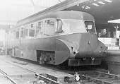
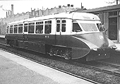
Numbers 2 to 4 were radically different on the inside from
the Picture bus 'inspired', more like borrowed, 2+3 seating arrangement with a
central gangway. These new vehicles were destined for an express business
service on the Birmingham - Cardiff route and as a result incorporated a buffet
bar which boasted hot and cold drinks, wine, a small selection of snacks and
hot food, thanks to a gas heated boiler which powered the coffee and milk
boilers, even a toaster! The interior also had the luxury of removable tables
and no less than two toilets, complete with hot water heated by the exhausts.
The mechanical underpinnings of the vehicles was again completed by AEC under
the capable direction of C.F Cleaver with each engine driving one bogie. All
the changes made for the first railcars in this second batch caused the price
to more than double compared to the prototype, Nos:2-4 costing £6,541.
However, the swish streamlining of the prototype,almost decorative buffers and
neatly concealed couplings (in the small panel that can just be made out in
between the buffers on the photo of No:4 above) remained on these railcars.
The first of the new 44 seat vehicles arrived at the
beginning of July 1934, undertaking several test runs including some especially
for members of the press to help publicise the new service which was launched
on the 16th July with the full compliment of three railcars (Nos:2-4). The
express Birmingham (Snow Hill)- Cardiff service represented the first regular
diesel working which ran to an express schedule in Britain; the 117½
miles travelled took just 2 hours 30 minutes, more than half an hour faster
than had previously been achieved by steam. This twice daily working continued
in the capable hands of Numbers 2-4 until 1940.
Mystery Tour delights
Although ordered as part of the same batch as the three
express railcars, the construction of railcars No:5 to 7 was delayed on account
of uncertainty over whether to opt for the short haul, high capacity type body
of the prototype, or trial a new setup all together. Eventually an order for
the bodywork for these vehicles was placed with the Gloucester Railway Carriage
and Wagon Co. Ltd, using the same under frames and mechanical underpinnings,
with very minor changes due to experience gained with the other railcars, as
the three eariler machines on the express service.
The new body builders introduced several significant changes
to the original bodywork including sliding doors, rather than the outward
opening doors on the other railcars to improve access as well as deeper windows
to improve the view for passengers, not to mention a variety of subtler changes
related to ventilation and the overall shape of the front and rear which only
enhanced the already aesthetically pleasing look of the earlier vehicles. These
new bodies were built to a similar short haul format as found on the prototype,
taking 70 passengers at a maximum speed of 70mph. The three railcars No:5-7
were delivered into service on the Oxford-Worcester line in July and August
1935, undertaking a variety of workings which encompassed London, Hereford and
Birmingham. However, in order to capitalise on the novelty of these undeniably
stylish vehicles, the first three Gloucester cars were employed on mystery
tours around Worcester on Sunday evenings which were extremely popular.
Thanks to the success of the railcars it already operated,
the Great Western placed another order with AEC in February 1935 for ten more
vehicles built to the same design and No:5-7. Six of the cars were almost
exactly the same, with 70 seater bodies, while a further two had the number of
seats reduced and a toilet installed in their place. These vehicles had further
modifications which the experience with running the railcars had shown to be
necessary, such as special oil coolers under the buffers at either end which
the earlier machines were subsequently fitted with as well. These railcars
found work in the West Midlands and West Wales.
Multi purpose unit
In the 1930s the Great Western's express passenger trains
were carrying large amounts of heavy parcels, particularly in the London area.
It became obvious that the passenger railcars the Great Western were now using
could equally well be used to take at least some of this heavy parcels traffic
away from the passenger trains, consequently allowing the express passenger
services to run faster and also reducing the need for shunting as Picture the
railcars could operate as fast, self contained vehicles. As a result of this
realisation, the last of the 10 railcars ordered in February 1935, No:17, was
built with virtually flush sides and three pairs of glazed doors that could
slide open to access the parcels space in between the two drivers cabs where in
the other railcars the passengers sat. This was the world's first diesel
parcels railcar, although the central space could just as well be filled with
milk churns, letters or newspapers. No:17 spent its days shuttling around
London and its suburbs, on some workings stopping at all stations between
Oxford and London to collect general traffic. Due to the great success of
No:17, later railcars Nos: 13 and 14 were also converted for parcels use too,
while a later machine, No:34 was also built specifically for parcels use but
with some significant changes including conventional railway draw gear which
made it far more versatile than No:17 as it could also pull parcels vans,
increasing its capacity greatly.
A load on my drawbar
Another experimental railcar was ordered along with the
other railcars in February 1935 - the GWR's centenary year-, however, No:18
made a radical departure from the sleek and streamlined 'flying banana'
railcars, as they were known, that had gone before it. From the outset this new
vehicle was designed to take a 60 ton trailing load and so received the
standard couplings and buffers found on any other railway vehicle, which rather
spoilt the streamlined appearance. To cope with the additional strain of
hauling a trailing load as well as moving its self, several key changes were
made to the underframes of No:18 including strengthening chassis members and
larger bogies since the streamlined valences were not fitted to this vehicle,
in any case the voice of experience showed that on the other vehicles the
streamlined valences were removed anyhow after a couple of months. In addition
the gearing was adjusted to suit the greater weight, both of the car itself
which was roughly 4tons heavier than Nos: 8-17 and to enable the machine to
pull the 60 ton trailing load it was required to and a set of reduction gears
were added behind the gearbox which could be selected to reflect the different
operating requirements of branch line or express operation, meaning in theory
the car could be used equally well on a branch line or on express work.
However, changes as a result of experience from the other railcars was also put
to good use, such as changing exactly how the two engines were positioned in
relation to each other or improving the ride quality by changing the
bogies.
To increase the small, 49 seat, capacity of No:18 it was
envisaged that it would be paired with a special trailer carriage of a similar
design to it with a cab at one end. However, in the event the control lines it
was fitted with were used to pair it with a standard auto-trailer coach instead
from the cab of which the railcar could be controlled. No:18 was fitted with a
Clarkson boiler which heated both the car and its trailer with heat from the
engine exhausts. However, No:18 was not just built on a whim, but was in fact
constructed with a particular service in mind; the Newbury - Lambourne branch
was a light railway that had opened in 1898 but by the 1930s was in need of
track renewal to allow large locomotives to use it, but the cost of the renewal
would not be recouped. Yet a light railcar like No:18 would take some of the
strain off the track and allow the use of the heavy steam engines to be
restricted to relatively infrequent freight services which the permanent way
could just about tolerate. The new railcar was delivered to the branch in April
1937 but was based at Reading and as a result its first working each day was to
deliver post dropped by Up Travelling Post Office to Basingstoke. The arrival
of No:18 on the Newbury-Lambourne branch transformed an operating loss into a
small proft, and this positive experience caused a seismic change in the
principal motivations behind the operation of the Great Western's diesel
railcars.
Let's go in house
By February 1938, the diesel railcars had more than proved
their worth, running almost 1 million miles in total, so it was not a surprise
when the Great Western Railway's chairman, Viscount Sir Robert Stevenson Horne,
announced to the company's Annual Meeting that a further 20 diesel railcars
were to be ordered. He added that although initially the idea had been to
supliment the exisiting steam services, where the railcars had ultimately
proved a victim of their own success and had to be replaced by higher capacity
steam hauled trains, or provide a service where it would not otherwise have
been economically viable to do so, like on the Lambourne branch, these new
vehicles were intended to replace steam trains on loss making services, as
shown by No:18 and its ability to haul a trailing load as well.
The arrangements for this batch of 20, the order for which
was placed in September 1938, differed from all the previous railcars, with AEC
only providing the engines, this time 105 BHP, 9.25L direct injection units
(chosen for greatest possible fuel economy), and transmissions while the under
frames, bogies, brakes and bodies were built at Swindon. As a result of the
invaluable experience with No:18, several major adjustments were made to the
design of the cars in this batch; the radiators were moved to being opposite
the engines and gearbox, allowing another fuel tank to be fitted, and the
positioning of the engines was reverted to the position found on the first 17
railcars to resolve the body sway experienced by No:18. However, undeniably the
most noticeable change was with the body work; gone were the elegant lines of
the 'flying bananas', replaced by Swindon's razor edges and flat panels. Not
all of the 20 vehicles were the same, however; Nos:19-33 were intended from
branch line work and fitted with 48 seats, and as a result of the success of
No:18's low gearing, all but Nos:19 and 20 had gearing permanently set to give
a maximum speed of 40mph. The two exceptions were fitted with duel range
gearboxes similar to the arrangement on No:18 which allowed running of upto
60mph or lower speed and more power to haul trailing loads and carry out branch
line work. As has already been mentioned, No:34 was built as another Express
Parcels vehicle. The new batch were three feet longer than their predecessors
and cost £6,240 each. No:20 was the first to appear from Swindon works in
June 1940, closely followed by Nos:19 and 21 in July that year. However, the
last four in the batch were quite special, so are deserving of a section all of
their own.
The real daddy of them all
The final four GWR diesel railcars are perhaps the vehicles
most closely related to the modern multiple unit which is so ubiquitous on
Britain's railways today and blazed a trail for British Railways to follow up
with their own multiple units in the late 1950s. Nos35-38 were designed to work
in multiple with each other and consequently each unit only had one driving cab
each so that when coupled together using the standard passenger gangway to walk
in between the two units there were two cabs at the outer ends of the set.
Together the two units could provide buffet and toliet facilities for 104
passengers, their combined seating capacity. However, the beauty of the concept
was that it was possible to place a standard GWR 3rd class carriage in between
the two units with control lines running through it to control both units from
either end, thereby increasing the capacity to 184. Mechanically each vehicle
was the same as the others in the batch with the four engines in the whole set
giving it a total of 420 BHP. However, the engines were geared differently for
those intended for branch line work which enabled these sets to operate at
speeds of upto 70mph. The first of the two twin sets was taken into service on
the Birmingham - Cardiff express service that had originally been operated by
Nos:2-4 in November 1941. These vehicles were configured so that one railcar
provided 60 seats, in two saloons, while the other boasted a 12 seat bar
buffet, luggage rack and 32 seats. Unfortunately by the time this set entered
service, wartime restrictions meant that all on-train catering was banned in
order to increase passenger accommodation, and, even with the additional centre
carriage they were unable to cope with the massive surge in demand for the
service after V.E day, leading to their replacement by steam hauled trains
except mid week, and eventual relegation to Bristol - Weymouth trains and
Reading - Newbury services for the other set which arrived in February
1942.
At Axbridge on 17th February 1947 one half of a double set,
No:37 received severe damage due to a fire, leading to standard railcar No:22
being commandeered to work with the other half of the set, No:38, inspite of
the fact, as you may remember, that No:22 was only geared for 40mph running.
This undesirable arrangement remained for seven years when in the Spring of
1954 railcar No:33 was rebuilt with a single cab to work in multiple with
No:38.
British Railways service
With the exception of two vehicles, incidentally both
damaged beyond repair by fire (the other was No:9, in 1945), all remaining 36
railcars passed into service with British Railways Western Region on
nationalisation in 1948 where they received a W prefix to their Great Western
numbers and smart Carmine and Cream livery for the passenger vehicles and
Crimson Lake for the Parcels railcars. As with the streamlined LNER A4
Pacifics, the streamlined railcars Nos:1-17 had their side valences over the
bogies removed for ease of access. Under BR the railcars remained carrying out
much the same duties as they had for the Great Western serving a wide variety
of branch line as well as secondary line destinations, ranging from Bewdley to
Ledbury. However, the railcars continued, as has been alluded to earlier, to
exhibit an unfortunate tendency to catch fire; with W10W joining the fire
casualty list in 1956 after catching alight at Bridgenorth, followed by the
double set of W35W/W36W just a year later near Bristol. The remaining railcars
soldiered on through the 1950s; experimental railcar No:18 migrating to the
obscure Llantrisant branch near Cardiff and a number of the razor edge Swindon
vehicles receiving a green livery similar to the early BR DMUs that were just
appearing. Meanwhile, the early streamlined railcars were slowly withdrawn;
No:2 being the first to go (but not through fire!) in 1954, followed by the
prototype and No:3 the following year. In fact, by 1960, none of the original
streamlined examples remained in service, while the second pioneer, No:18 was
pensioned off in 1957 with parcels railcar No:17 following in 1959. As the
branch lines they served in Wales steadily closed, the remaining ex GWR
railcars were moved to the London area where steam crews were becoming less
readily available. The railcars also managed to find their way back to their
old Worcester stamping ground in their penultimate year in service, 1961 and
other examples working in the Severn Valley and around Tenbury Wells. The
railcars final year in traffic was 1962; all 13 remaining examples had been
withdrawn by October that year.
Conclusions
Overall, it seems fair to say that C.F Cleaver had a pretty
good idea, one that only got a bit greater with later refinements from the
Great Western Railway which arguably was the forerunner of all modern multiple
units on Britain's railways today and it is marvellous that we can still enjoy
their charm in the preserved examples today. However, in some respects the AEC
railcars were a victim of their own success, becoming so popular they had to be
replaced by the steam trains they'd been intended to supplement. Yet, with
No:18 the railcar and later the DMU found their niche; lightly used branch
lines where they might have been able to help turn a profit. Christian Wolmar,
in his book 'Fire and Steam', even goes as far to suggest that an earlier and
more widespread adoption of the concept that was shown to be possible by these
railcars might have helped save lines which fell under Dr Beeching's infamous
axe in his 1963 report, one year after the last of GWR's pioneering railcars
were withdrawn....
For reference sources please visit
www.totally-transport.co.uk/gwr-aec-railcar.html
Specifications of GWR Railcar No 1
| Engine(s) |
One engine - 8.85 litre AEC diesel |
Length over buffers |
63 feet 7 inches |
| Bogie centres |
40 feet |
Bogie wheelbase |
7 feet |
| Seating capacity |
69 seats |
Fuel tank |
45 gallons |
| Weight |
24 tons 0 cwt |
Maximum speed |
63 mph |
Specifications of GWR Railcar Nos 2 to 4
| Engine(s) |
Two engines - 8.85 litre AEC diesel |
Length over buffers |
63 feet 7 inches |
| Bogie centres |
40 feet |
Bogie wheelbase |
7 feet |
| Seating capacity |
44 seats |
Fuel tanks |
2 x 45 gallons |
| Weight |
26 tons 4 cwt |
Maximum speed |
80 mph |
Specifications of GWR Railcar Nos 5 to 7
| Engine(s) |
Two engines - 8.85 litre AEC diesel |
Length over buffers |
63 feet 7 inches |
| Bogie centres |
40 feet |
Bogie wheelbase |
7 feet |
| Seating capacity |
70 seats |
Fuel tanks |
2 x 45 gallons |
| Weight |
25 tons 6 cwt |
Maximum speed |
80 mph |
Specifications of GWR Railcar Nos 10, 11 and 12
| Engine |
Two engines - 8.85 litre AEC diesel |
Length over buffers |
63 feet 7 inches |
| Bogie centres |
40 feet |
Bogie wheelbase |
7 feet |
| Seating Capacity |
63 seats for railcars Nos 10, 11 and
12 |
Ditto |
Ditto |
| Weight |
29 tons 18 cwt for railcars Nos 10, 11 and
12 |
Ditto |
Ditto |
Specifications of GWR Railcar Nos 8, 9, 13, 14, 15 and
16
| Engine |
Two engines - 8.85 litre AEC diesel |
Length over buffers |
63 feet 7 inches |
| Bogie centres |
40 feet |
Bogie wheelbase |
7 feet |
| Seating capacity |
70 seats for railcars Nos 8, 9, 13, 14, 15
and 16 |
Fuel tanks |
2 x 45 gallons |
| Weight |
29 tons 10 cwt for railcars Nos 8, 9, 13,
14, 15 and 16 |
Maximum speed |
80 mph |
Specifications of GWR Parcel Railcar No 17
| Engine |
Two engines - 8.85 litre AEC diesel |
Length over buffers |
63 feet 7 inches |
| Bogie centres |
40 feet |
Bogie wheelbase |
7 feet |
| Loading capacity |
10 long tons |
Fuel tanks |
2 x 45 gallons |
| Weight |
28 tons 17 cwt for railcar No 17 |
Ditto |
Ditto |
Specifications of GWR Railcar Nos 19 to 33
| Engine(s) |
Two engines - 9.25 litre AEC diesel |
Length over buffers |
65 feet 8 inches |
| Bogie centres |
43 feet 6 inches |
Bogie wheelbase |
8 feet 6 inches |
| Seating capacity |
48 seats |
Fuel tanks |
4 x 45 gallons |
| Weight |
35 tons 13 cwt |
Maximum speed |
70 mph |
Specifications of GWR Railcar Nos 34
| Engine(s) |
Two engines - 9.25 litre litre AEC
diesel |
Length over buffers |
65 feet 8 inches |
| Bogie centres |
43 feet 6 inches |
Bogie wheelbase |
8 feet 6 inches |
| Loading capacity |
10 tons |
Fuel tanks |
4 x 45 gallons |
| Weight |
35 tons 13 cwt |
Maximum speed |
70 mph |
Specifications of the two GWR Twin-sets, Railcar Nos 35
& 36 and 37 & 38
| Engine(s) |
Four engines - 9.25 litre AEC diesel |
Length over buffers |
65 feet 8 inches |
| Bogie centres |
43 feet 6 inches |
Bogie wheelbase |
8 feet 6 inches |
| Seating capacity |
104 seats |
Fuel tanks |
8 x 45 gallons |
| Weight |
74 tons 6 cwt |
Maximum speed |
70 mph |
back to top
|