LMS Route: Evesham to Birmingham
GWR Route: North Warwickshire Line
GWR Route: Banbury to Wolverhampton
Birmingham New Street - Southern Approaches:
mrbhm_sa1892
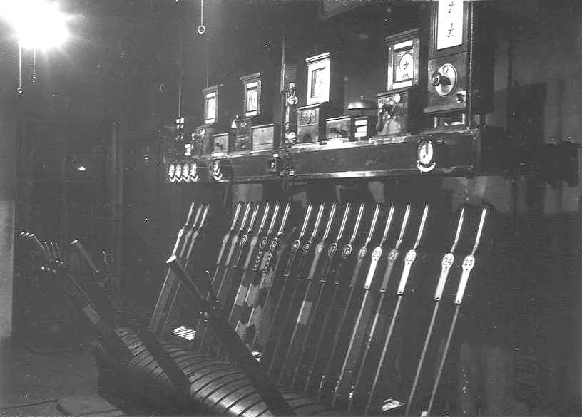
Night time internal view of Bordesley Junction Signal Box
showing the various levers for the signals, the junction points and detonators
on 31st March 1954. This photograph is on Mark Norton's
website which
celebrates his fathers photography of railway and non-railway subjects. Simon
Foster wrote an explanation of the photograph which is also provided below.
The levers which have reversed (pulled over in the frame)
are numbers 4, 5, 6, 13 & 23. 4 ,5 & 6 having been pulled that the line
has been cleared for a Down train towards Camp Hill, and Signal 23 (Up Home
from Camp Hill) is also clear. Lever 13 is the Facing Point Lock (FPL on the
diagram) for the junction points No 14. This is a large bolt which holds the
point blades in position whilst a train is passing over them. This lever would
have be put Normal (back in the frame) before the points could be changed to
send a train to the GWR, and then pulled again before the signal lever (No 2 or
3) could be pulled to clear the signal itself. Levers 11 and 12 are painted
with distinctive black and white chevrons, indicating that they operate
detonator placers.
These are mechanisms which put a small metal can containing
gunpowder on the top of the rail, this explodes under the train wheels to give
a warning to the driver in case of emergency, such as a train having passed a
signal at danger. The chevrons point up or down the lever according to the line
to which they apply. The instrument shelf above the frame (also known as the
blockshelf) carries a number of vintage Block Instruments, which are used to
control an indicate the state of the line between the signal boxes (the Block
Section), ie, whether or not the section is occupied by a train, or if the
signalman at the next box has given permission for a train to be sent to
him.
Four of the instruments are of Midland Railway origin,
whilst the right hand one is of the L&NWR pattern. Between the MR
instruments are the separate bells for communication to the signalboxes either
side, the tapper key is on the front is used to ring the bell in the next box.
The L&NWR instrument has its bell built into the base under the main body
of the instrument, the bell tapper key is in the bottom right corner of the
instrument body. Two of the MR instruments have commutator handles on the
front, these are known as "Pegger" (or Pegging) instruments. The other two are
"Non-Peggers" To communicate with each of the adjacent signalboxes requires a
Pegger snd a Non-pegger. The Pegger instrument commutator operates its own
needle (in the dial above the commutator), and the one on the associated
Non-Pegger instrument at the adjacent signalbox. Similarly, the Pegger at the
adjacent box operates the Non-Pegger instrument needle at this box.
The MR used separate instruments for each line, whilst the
L&NWR used combined instruments, with two needles combined into one case,
along with the Pegger handle (the wheel on the front). The lower needle is the
Pegger. Both needles on the L&NWR instrument look like they are in the
"Train On Line" postion, meaning that there are trains on both lines betwen
Bordesley and the GWR. Normally, and for obvious reasons, only one train is
allowed in each section between signalboxes. However, the L&NWR instrument
is of the "Permissive" type. These were used where it was necessary to permit
more than one train to occupy the section between signalboxes, typically on
busy Goods lines.
Above the commutator handle on this istrument is a small
circular window, which shows the number of trains in the section (in this case
the number of trains coming from the GWR towards Bordesley). To warn the driver
that he is entering a section which is already occupied by one or more trains,
a Subsidiary signal is provided. This has a smaller arm than a normal one, and
is placed under the Main signal for the same line. You can see this on the
diagram - Signal 2 is the Main arm for the GWR line, if this is cleared the
driver knows that the section is clear of other trains, if the small Subsidiary
arm (No. 3) is cleared instead, it indicates that the section is already
occupied, so he needs to proceed with caution and to be prepared to stop on
sight of any train ahead.
Signals reading into the section toward the adjacent box
are controlled such that the signalman at Bordesley cannot clear them unless
the adjacent signalman has given him permission to do so, by accepting the
train on the relevant block instrument (giving a "Line Clear"). This is the
meaning of the "Released By Block" note you can see against several signals on
the diagram. The levers controlling such signals also have a white band painted
on them to indicate that they cannot be pulled unless the block instrument
shows "Line Clear". The round instruments on the front of the block shelf are
signal and track circuit repeaters. For signals, these are provided where the
signal is out of sight of the box, and prove to the signalman that the arm has
responded correctly to the movement of its lever.
Simon Foster
 back back

|