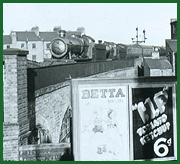
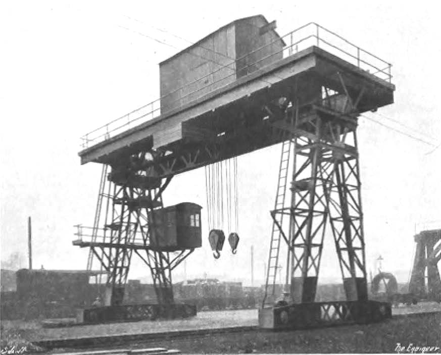
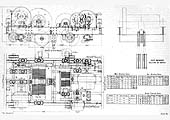
Small Heath and Sparkbrook Station's 20-Ton Goliath CraneThe following article about the 20 ton electrically powered travelling gantry crane installed at Small Heath down goods yard in early 1925 has been transcribed from ‘The Engineer’ magazine dated 12th June 1925. The crane was brought it use in March 1925, see GWR Goods Department circular at 'gwrsh3158'.20-Ton Goliath CraneWe illustrate herewith a 20-ton electrically-driven Goliath Crane, recently designed and built by S. H. Heywood and Co., Ltd., engineers of Reddish, near, Stockport, for the Great Western .Railway Company, for use in that company's yard at Small Heath. The crane travels along two rails fixed at 40ft. centres, the total length of the track being 360ft. The main bridge, consisting of two main girders and two auxiliary girders (see 'gwrsh3215') is carried on legs of such height as to enable the crane hook to hoist up to a height of 22ft. above the level of the tops of the rails on which the crane travels. The travelling motor (see 'gwrsh3216') which is carried on a stout channel framework built between one of the main girders and the adjacent auxiliary girder, has a full load capacity of 23 brake horsepower, and the power is transmitted through a pair of high carbon steel spur wheels to a horizontal shaft 2¾in in diameter, which extends the full length of the bridge, and is coupled by means of bevel wheels to the two vertical driving shafts, which are supported by the crane legs driving the steel travelling runners through a further pair of steel bevels. The runners are double flanged, each consisting of a cast iron centre having shrunk upon it a rolled steel tire.
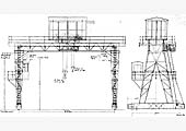
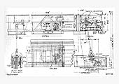
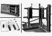
As the lower pairs of bevel gears work with practically no clearance between the engaging teeth, any appreciable wear in a vertical direction of the bearings supporting the weight of these shafts will throw the whole weight of the latter on to the teeth of the bevel wheel. These shafts are therefore supported in large Hoffmann ball bearings, the weight being transmitted from the shaft by mans of a steel collar resting against the shoulder turned on the shaft itself. To ensure that the weight of these shafts is taken simultaneously by all balls in the bearings, the ball races are made to and rest in spherical washers. The travelling speed of the crane when carrying its full rated load of 20 tons is 100ft per minute. In order to facilitate the travelling of the crane, Messrs. Heywood have fitted on the travelling crane motion one of their solenoid actuated brakes, which operates on a steel drum keyed to the motion spindle A platform is provided all round the top of the crane. It is supported by brackets fixed to the main girders, and is protected by a substantial handrail, which finishes at places on the platform where the two access ladders are arranged. An important feature of this platform is that at one end of the crane it has been made strong enough to bear the weight of any single part of the crab should it be necessary at any time to remove any such part for the purposes of inspection, renewal or repair. The main lattice girders which carry the crab are of great strength and are very rigidly connected through the two legs to the two end carriages, the whole being substantially constructed and braced with a view to preventing racking or twisting of the crane when travelling with the fully loaded crab at either extreme limit of its traverse. The crab which is shown in detail in 'gwrsh3217' consists of a framework built up of rolled steel sections heavily gusseted and riveted together so as to form a rigid structure for sustaining the load and carrying the necessary motors and gearing. It is provided with two entirely separate hoisting motions, each consisting of a barrel driven through spur gearing by an electric motor, each motion being provided with its own steel wire rope and bottom block. Each motion is driven by its own 23 brake horsepower motor, the main hoisting motion being capable of lifting the full load of 20 tons at a speed of 10ft per minute, whilst the auxiliary motion is capable of lifting a load of 5 tons at a speed of 30ft per minute. The motors are fitted with Heywood’s patented series wound brake operating on a brake drum keyed to the spindle of the motor itself. The motions are fitted with a patented auto-replacement over winding switch, so that if, through inattention on the part of the operator, the load is hoisted dangerously high, the current supply of the motor is cut off and the brake instantaneously applied. On the hoisting controller being moved over to the lowering side the brake is again lifted and the brake descends, the switch automatically resetting itself against a further over-wind. The cross traverse motion which drives the crab at a full speed of 60ft per minute is effected by a 6½ brake horsepower motor, and this motion is fitted with a solenoid operated brake. It will be realised that the use of an automatic brake on this motion calls for great stiffness and rigidity in the legs, and any other attachment to the main bridge, as the sudden stopping of the heavy crab combined with the load possibly hanging on the hook, is liable to cause very serious swaying, unless the accompanying stresses are taken into consideration in the design. The actual framework of the crab is extended on two sides so as to form a platform. Another feature of this crab is that there is incorporated in the design of the framework a rolled steel joist reaching the full length of the crab and projecting several feet beyond it. Suspended from a trolley running on the bottom flange of this joist is a pair of chain blocks of 1½ tons capacity. This arrangement makes possible for the heaviest individual article on the crab frame to be picked up, and when the crab itself is brought up to the platform on the crane, the load can be travelled out beyond the crab and lowered on to the platform, which was referred to earlier in this article as having been specially strengthened up to carry the largest single piece on the crab itself. The whole of the crab is enclosed by a substantial framework covered with galvanised corrugated steel sheets, large access doors being provided. The four controllers which operate the four motions of the crane are, of course, fixed in the operator’s cabin, which, as is shown in the photograph, is carried on one of the legs of the crane, with the ladder and platform provided for easy access. An interesting feature in connection with the operation of this crane is the employment of the Heywood resistance system, which we are able to illustrate in the first two photographs in 'gwrsh3218'. The cabinet containing the resistances is of the enclosed ventilated type. Immediate access can be given to its interior by means of sliding doors, which expose the whole front of the box. It will be observed that each individual porcelain bobbin carrying the resistance wire can readily be removed from the box by disconnecting the supply wires and turning the thumbscrew which holds the bobbin in position. It will also be noted that, when the sliding doors are open, the whole of the wire of any one bobbin can be easily seen. The second photograph shows the separate elements comprising one of the resistances. Another feature of interest in this crane is the employment of the Heywood patented system of cage wiring. In this connection a spacious cast iron trough (see final photograph in 'gwrsh3218') is run round one side of the cage and a cast iron pipe runs from each controller down to the trough. Large cast iron doors give access to the conductors. The doors are held by two thumbscrews only, which are permanently fixed to the cover, so that they cannot be lost. To prevent the doors being accidently pushed over the edge of the cage floor they are secured by chains. The terminals in the resistance cabinet for each motor are grouped together and clearly marked, the numbers on each terminal corresponding to the numbers on the controller fingers. By picking up any cable in the trough and jerking it slightly, the circuit can be clearly seen at once between the controller finger and the particular resistance unit. With this system it is almost impossible for the crane driver to injure the conductors, and he can put his feet in the most comfortable position without the fear of doing any damage. The total temporary deflection on the crane girders with the crab in the centre of the girders when lifting a test load equal to 25 per cent overload was 7/16 inch.
|
||||||||||