|
|
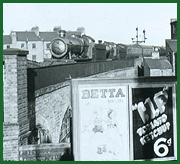
GWR Article
Electrical Labour-Saving Equipment at Moor Street
Station
Great Western Railway Magazine Vol XXIX No 5 published
May 1917.
We gave, a few months ago (Part 3), a general description of
the Great Western Railway station at Birmingham, Moor Street. This station is
of more than ordinary interest, as it comprises several unique features. The
most noteworthy characteristic is that the goods depot consists of two
low-level sheds in addition to a shed and yard on the level of the railway
lines and passenger station. The passenger station, which was opened on July
1st, 1909, was projected before the provision of the goods depot was
contemplated. Owing to the configuration of the ground at the site, it is built
on a brick viaduct, the northern end of the station abutting Moor Street,
which, from that point southward, falls away rapidly. To support the high-level
goods yard alongside the passenger station, the viaduct was widened as a
ferroconcrete structure designed to serve also as a low-level goods station. On
the low level are two sheds (known as Shed A and Shed B), which are separated
by Park Street. Due to the natural fall of the ground Shed B is about 8 feet
lower than Shed A. The relative positions of the high and low level premises
are shown in the accompanying sectional drawing (see 'gwrms1204').
The peculiar situation of the accommodation naturally
dominated the design of the equipment provided for dealing with the traffic
passing to and from the several sheds. Further, the modern tendency in the
development of expeditious goods handling, of bringing the loading and
unloading machinery to the wagons, instead of bringing wagons to fixed cranes,
was followed wherever possible. The result is that at Moor Street is to be
found a variety of electrical traffic handling appliances of the most
interesting and up-to-date type. The supply of electricity is taken from the
Birmingham Corporation.
Dealing first with the high level accommodation, designed
primarily to deal with perishable market traffic, and after this is dealt with,
with general traffic, the covered goods shed in the yard comprises under one
roof two long sidings, a platform beside one of these sidings and a cart road
between the platform and the other siding. The platform and the siding beside
it are served for a length of 400 feet by an overhead travelling crane made by
Messrs Royce Ltd of Manchester. The travelling bridge with a span of 28 feet
4½ inches moves at an average speed of 250 feet per minute and carries a
traversing carriage with an underhung revolving jib below it, the jib having a
radius of 16 feet. The carriage with its jib traverses the shed at a speed of
70 feet per minute, while the jib revolves at a speed of two revolutions per
minute and the hoisting gear raises and lowers a load of one ton at an average
speed of 33 feet per minute. The combined action of travelling the bridge,
traversing the carriage with the jib, and sluing the latter can take the load
to or from any wagon in the siding from or to any cart in thee cart road. Two
covered openings in the shed platform are provided through which goods in
special crates can be raised from or lowered to the low-level sheds A or B. The
electrical equipment was made by the British Westinghouse Company.
Outside the high-level shed is a fixed jib crane capable of
raising and lowering a load of six tons. The gear can raise and lower its full
load at a speed of 20 feet per minute, and slue it at a speed of two
revolutions per minute, the jib radius being 15 feet. An automatic electric
brake is fitted to the hoisting gear, while provision is made for lowering
either by a separate hand-lever brake or by the use of the motor itself as an
electrical brake. The crane was made by Messrs Stothert & Pitt, the
Electric Construction Company providing the motors, and Messrs Allan West the
controllers and resistances.
For marshalling the goods wagons, which are raised to or
lowered from the low-level Shed B by a 20 ton lift (referred to hereafter), the
north-east end of the yard is provided with a 25 ton bridge traverser. It is
designed to transfer wagons between three parallel lines of rails, the wagon
being hauled on to or off the traverser by an electric capstan. The traverser
was made by Messrs Ransomes & Rapier. Thirteen Clyde capstans and a large
number of reels are disposed in the yard to haul wagons, either singly or in
trains, to and from the 20 and 30 ton wagon lifts, the 6 ton crane, the long
siding beside the covered platform, and two turntables at the Moor Street end
of the yard. The rope used on a Clyde capstan is never handled by the capstan
man except to unwind it from the barrel and haul it to the wagon, which can be
done by the hook. This allows steel ropes to be used instead of hemp ropes,
which must be used where the rope slips on the barrel and the capstan man hauls
in the slack. The consequent saving in the annual cost of ropes, and in the
labour of handling hemp ropes when wet, is remarkable. All these capstans have
been made by Messrs Stothert & Pitt, and the switchgear by Messrs Morris
& Lister. The squirrel cage motors were provided by the Electric
Construction Company.
In the low-level sheds, A and B, there are fourteen similar
capstans. Four in Shed A to serve the 30 ton lift and traverser and the
sidings, and ten slower speed capstans in Shed B where the number of sidings is
greater. All the necessary reels for guiding the capstan ropes are provided.
The electric equipment for the capstans in Shed B was provided by Messrs
Crompton & Company.
Shed A contains only two long sidings for which power
appliances are needed. Between the sidings which run for a distance of 285 feet
at right angles to the cart entrance from Park Street, are two platform, one
beside each siding and a broad cart road between the platforms. A cross
platform at the Moor Street end (farthest from the Park Street entrance)
connects the two long platforms, the whole forming a U shaped continuous
platform. Here a walking jib crane has been provided, which runs on a one-rail
U-shaped track extending down each platform, forming the legs of the U, and
round the cross platform. The crane hoists and lowers its full load of 30 cwt
at a speed of 40 feet per minute, and slues the jib at a speed of 2.5
revolutions per minute. The crane travels at a speed of 250 feet per minute on
the straight, and the jib radius of 18 feet allows of anything within reach on
either platform being transferred to a cart backed against the platform or vice
versa. The crane and top guide with its three conductor wires was made and
erected by Messrs Babcock & Wilcox, the motors were provided by Messrs
Harding Churton & Company and the controllers by Messrs Allen West.
A 30ton lift is provided in each shed to transfer wagons
between the high level yard and the shed. The 30 ton lifts serving the two
sheds A and B are similar in all respects except the height of lift. In the
lift for shed A the distance between rail level in yard and the shed below it
is 24 feet 1½ inches. The cage can take a wagon 25 feet over buffers and
weighing 30 tons. Such a wagon has been raised and lowered at an average speed
of 128 feet per minute. The lifts were made by Messrs S H Heywood &
Company, three phase motors being provided by the Lancashire Dynamo Company and
semi-automatic switchgear by Messrs Electric Control Ltd.
The switchgear is worked by means of a master controller in
the cage. Its handle is interlocked with disappearing rail stops on the cage
rails. The controller handle cannot be moved until the rail stops have been
raised, after the wagon is in position, to prevent its movement either way in
the cage. Other safety devices consist of automatic gear to hold the cage
should any of the ropes break or stretch unduly. Limit switches are provided to
prevent over travel of the cage either at the top or bottom which act first on
the control gear and should this fail a second switch cuts off the main
supply.
In Shed A wagons are transferred from the lift to the
sidings or from the sidings to the lift by a 30 ton wagon traverser. The
sidings on either side of the cart road are 100 feet apart, and only these two
sidings are served. It was decided to drive the traverser by an induction motor
of the one speed cascade type, as made by Sandycroft Ltd, arranged to creep
while exerting full load torque. This latter feature has proved most useful in
aligning the traverser rails with the siding or lift cage rails. The traverser
was made by Messrs S H Heywood & Company. The traverser can travel the
whole width of the shed with a 30 ton load at an average speed of 275 feet per
minute. A capstan with head fixed to the gearing and using a slipping rope is
provided for hauling wagons on to and off from the lift cage. It is worked by a
Sandycroft squirrel cage induction motor with special high resistance motor
windings to give great starting torque for moderate current expenditure. It can
give a pull of 750 lb at 300 rpm. and a maximum pull of 2,000lb.
Shed B is served by a 30 ton lift similar to that already
described. The distance between rail level in the high-level yard and that in
the shed is 33 feet 4 inches, and the average speed of raising and lowering a
30 ton load is 137 feet per minute. Shed B is further provided with a 20 ton
lift at the corner opposite to the 30 ton one. This lift was built by Sir
William Arrol & Company, the British Thomson Houston Company providing the
electrical equipment. The height of the lift is 33 feet 4 inches, and the
average speed when raising and lowering 20 tons is 145 feet per minute.
Shed B is provided with eight parallel lines of sidings some
of which are only a few feet apart. A 30 ton wagon traverser runs the whole
width of the shed for 256 feet at the Park Street end. The perishable market
traffic dealt with in the early morning in this shed requires the most rapid
handling possible. This accounts for the high speed of the large lifts and it
is essential that the traverser should not only have a correspondingly high
speed but be able to stop very accurately at any of the sidings. This is
accomplished by the use of Hele Shaw oil pressure transmission gear. By turning
a hand wheel the traverser can be stopped or started in either direction and
the rapid acceleration and high maximum speed obtained (the average speed with
a 20 ton load for the journey of 220 feet being 350 feet per minute) and
combined with the slowest possible creeping speeds and rapid reversing for
secure rail alignment.
There being two lifts to serve at opposite sides of the
shed, two traversing carriages, each to take a wagon, are necessary. Each of
these carriages has been made detachable from the central locomotive, automatic
couplings being provided to quicken the process of attaching and detaching. The
locomotive part of the traverser is able to haul both traversing carriages, one
empty and the other being loaded, at an average speed of over 300 feet per
minute for the whole journey. The traverser was made by Messrs. Stothert &
Pitt and the motor by Messrs Crompton & Company, British Thomson Houston
controllers being used. The Hele Shaw transmission gear was made by Messrs
Compayne Ltd.
The sidings, lifts and traverser are worked by ten Clyde
capstans of the same type as described for the high-level yard. The central
loading platform in Shed B is provided with two 1 ton fixed jib cranes, either
of which can deliver goods from wagons in the siding beside the platform to the
cart road on the other side of the platform or vice versa. These cranes were
made by Messrs Stothert & Pitt. They can raise or lower loads of one ton at
an average speed of 30 feet per minute and slue the load at a speed of two
revolutions per minute. The motors were supplied by the Electric Construction
Company and the controllers by Messrs Allen West & Company. The load can be
lowered by a hand brake or by using the motor as a brake, and the sluing motion
is stopped buy a pedal brake. The whole of the electrical machinery at Moor
Street was made to the drawings and specifications of Mr Roger T Smith, the
Electrical Engineer to the Great Western Railway.
|