|
|
 |
|
|
GWR Route: Banbury to Wolverhampton
Acocks Green & South Yardley Station: gwrag3992
Although the new Acocks Green & South Yardley station
had opened in January 1907, the footbridge at the south end of the station was
not constructed until 1911. This internal letter dated 10th June 1911 is from
Mr A Blackall (Signal & Telegraph Engineer based at Reading) to Mr S
Johnson (Divisional Superintendent of the Line based at Snow Hill Station,
Birmingham). The newly constructed footbridge at the Station had obscured the
signalman’s sight of both the Down Main and Down Relief Starting Signals.
The new Signal Box (opened in January 1907) was located at the bottom of the
ramp at the Leamington end of the down island platform (from 1913 this became
the relief island platform) and the down starting signals were at the opposite
(Birmingham) end of the station. These signals can be seen in 'gwrag1069' and 'gwrag19a'.
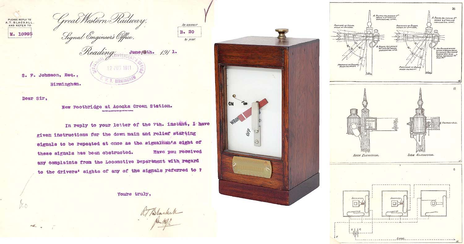
The photograph shows a Signal Repeater Instrument and the
diagrams are from the Great Western Railway’s Electrical Department –
Book of Diagrams. The selected diagrams show the semaphore signal arm limits,
the location of the contact box on the signal post, and the wiring of a typical
single arm contact box.
Signal Repeaters were introduced around 1900. They used
contact boxes on the signal posts to detect the physical position of the
semaphore signal arm. A centre tapped electric battery was used to identify if
the signal was within 5o of the horizontal or lowered to between 45o and 80o
(latter signal spectacle designs specified 55o and 80o). Signal arms within
these limits returned either a positive or negative value to solenoids in a
signal repeater instrument in the Signal Box. The solenoids operated the
indicator arm in the instrument to the corresponding ON or OFF positions. If
the semaphore arm was outside these limits (or the electrical wires became
broken) the repeater indicator arm would fall by gravity to an intermediate
position labelled WRONG.
Robert Ferris
 back back
|
|
|